
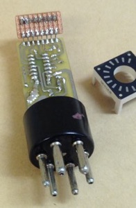
2023-04-03 Update: The circular LED bargraph display that I used for this project is no longer available from the original Ebay sources, and I haven't found any other source. Therefore, for anyone interested in building this, you'll need to locate a suitable replacement part, or custom build a display using discrete LEDs.
A project that’s been sitting on the back burner for a while has finally come to fruition. I’ve been contemplating construction of a solid state replacement for a 6U5 and 6E5 magic eye tube. These tubes were used as tuning indicators in radios of the 1930’s and 1940’s. While the 6E5 is still available at reasonable prices, they have a very short life. For a radio that is used regularly, I thought it would be nice to have something that I wouldn’t have to worry about burning out. The sticking point in this project was the availability of a suitable circular LED bargraph display. Recently, some became available on Ebay, and I bought a couple of them to experiment with. They have 15 green LEDs arranged in a 300° arc, and one red LED located in the gap of the arc. I would have preferred to have twice as many LEDs, but this display was the best I could find. On the positive side, the diameter of the display is a nearly perfect match for a 6E5/6U5. Below is a side by side comparison of an original 6U5 and the solid state replacement.
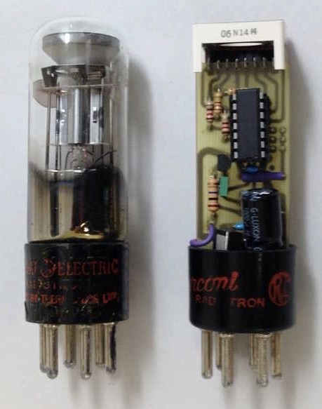
See the bottom of this page for a link to the schematic. The circuit is based on a PIC16F684 microcontroller and a JFET input buffer. The JFET buffer provides a very high input impedance to match that of a vacuum tube, and in addition, it provides a means to measure the radio AVC voltage which can swing outside the range of the microcontroller power supply. Power is derived from the radio’s tube filament supply (pins 1 and 6 on the tube base). It should be noted that this circuit uses a positive ground, and assumes that one side of the filament is grounded, and that the eye tube cathode is also grounded. This is generally the case in most receivers using eye tubes. However, there were occasionally centre tapped filament windings where the centre tap was grounded. For receivers of this type, some circuit modifications would be required.
Following is a video showing the breadboard prototype of the solid state eye tube in operation:
Following is a video of the solid state eye tube in operation, installed in a General Electric JK-96 console receiver:
The LED bargraph display was manufactured in China and has a part number 4000–0600–0124. I was not able to determine the manufacturer. There is no guarantee that there will be a continued supply of the LED bargraph display that was used in this prototype, but the circuit could be adapted to other LED displays which may become available from time to time.
Project Files:
As mentioned at the top of this page, the LED display is no longer available. Following, for historical purposes only, are the links to the original Ebay listings.
http://www.ebay.com/itm/251437248842/
http://www.ebay.com/itm/121382061132/
http://www.ebay.com/itm/251271532668/
If I manage to locate a new source for these parts, I'll update the listing.
Following are several additional photos showing some construction details.


Note the small piece of stripboard and 8-pin socket header mounted to the LED output solder pads on the main PC board. This allows for some side to side adjustment of the display position so that it may be centred relative to the tube base.
Also in the upper left photo, note that the three jumpers J1, J2 and J3 (immediately to the left of the microprocessor) are not used at present. I’ve provided solder pads for them to allow for possible future use in setting configuration options with future software revisions.
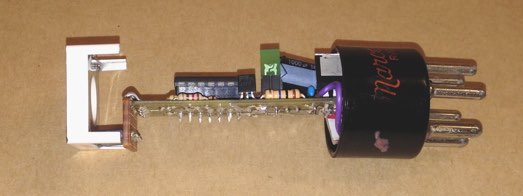
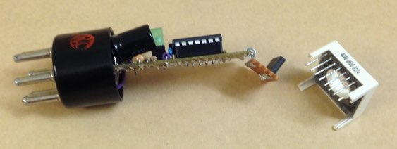
Also note that the 1000 µF electrolytic capacitor is bent over to avoid interference with the tube base. It should be mounted with enough free lead length to allow for it to sit out of the way.
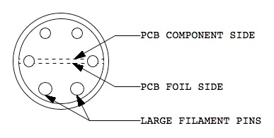
The following diagram shows how the circuit board should be oriented in relation to the tube base, in order to have the same display orientation as a real 6U5 or 6E5.
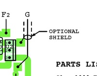
If you refer to the printed circuit layout files, there is a solder pad shown for a shield, if using an optional shielded grid conductor (see below). It won’t normally be necessary to use a shielded grid lead if the entire assembly is being mounted in a tube base with short leads. However, if for some reason, you need to run the grid lead a considerable distance, it may be advisable to use a shielded conductor because of the circuit’s extremely high input impedance which can be susceptible to hum pickup.
One final note of caution: Pay close attention to the polarity of the 1000 µF electrolytic capacitor and the two rectifier diodes. Because this uses a 7905 negative regulator to produce a positive ground supply, the component polarities are the opposite to what is normally encountered.
As this project continues to generate interest, here are more details.
Please Note:
I’ve had several requests from people asking if I could sell them a preprogrammed PIC microcontroller. Unfortunately, it’s just not practical to do this. My cost to mail one of these chips is prohibitive due to Canada Post’s rates. The microcontroller is too thick to qualify as letter mail, and the cheapest parcel rate even for something this small is far too expensive. It is cheaper to buy a PICkit2 programmer from Ebay sellers (going rate is about $8.00 with free shipping) and program it yourself. Though I recommended the PICkit3 programmer above, the PICkit2 is perfectly adequate for programming everything but the newest PIC’s.
Hobbyists familiar with old radios are not necessarily familiar with microcontrollers. So, here is some info on how to program them.
First of all you need the program code hex file. You can download that from the link given above on this page. You will also need two other things:
A programmer (PICkit2 or PICkit3);
Programming software (MPLAB or MPLAB-X).
For the programmer, there are a few options available, but I recommend the PICkit3 programmer from Microchip (the maker of the PIC microcontrollers). It is available directly from Microchip, as well as major electronics distributors such as Mouser and DigiKey. Currently (September 2016), it costs about $48.00 (US dollars). Other brands are available and are marginally cheaper, but for reasons which should be obvious, I recommend buying the programmer that’s made by the same company that makes the chips.
The programming software, MPLAB-X, is free and can be downloaded directly from the Microchip website. It is cross platform. There are versions available for Windows, Macintosh and Linux. MPLAB-X is a complete development package that allows you to write your own software in C or Assembly language and then compile/assemble it, and finally download it into the PIC microcontroller. Since the 6U5/6E5 software has already been written, assembled and saved as a hex file, MPLAB-X is only required for the PIC programming operation. I won’t go into the details of using MPLAB-X, because there is documentation available for it on Microchip’s website, and there are a lot of microcontroller support sites on the Internet which have far more detailed information than I could possibly provide.