On my webpages there are several construction projects for low power medium wave broadcast band AM transmitters. These transmitters generally fall under the FCC Part 15 rules in the USA, and the Industry Canada RSS-210 rules here in Canada. The Canadian and US regulations are essentially the same, limiting output stage power to 100 mW and antenna length to no more than 3 metres (10 feet). These constraints ensure that these transmitters will have an effective range of no more than about 30 metres (100 feet), which is perfectly fine for experimentation, and broadcasting music to your antique radio collection.

However, this is where some problems arise. It’s not particularly difficult to build a low power transmitter using a handful of electronic parts. But, getting that signal to radiate out of a 3 metre (or shorter) antenna is another matter entirely. A lot of hobbyists build various low power transmitter projects, and can’t get the signal to travel more than a couple of feet. So, they assume that they need more power. Wrong! It’s an antenna matching problem in nearly every case. Matching a transmitter to an antenna is more involved than simply connecting a piece of wire to the transmitter output. On my transmitter webpages, I’ve been guilty of glossing over antenna matching details. And after receiving a couple of comments in that regard, I’ve come up with this short tutorial on antenna matching. This is not going to be a rigorous treatment by any means. I will present a number of formulae without any background derivation, but at least this will cover the important aspects, and the reader can then refer to more detailed sources for additional information.
There are a few different definitions of an electrically small antenna. One of them is “an antenna whose largest dimension is less than 1/10 of the its operating wavelength.” By that definition (and others as well), the 3 metre antenna on a Part 15 AM band transmitter is most certainly electrically small. Electrically small antennas present a few difficulties which will be discussed here. On the other hand, the fact that they are physically much smaller than the wavelengths at which they operate, means that they can be analyzed using basic circuit theory, rather than having to resort to specialized antenna software.
For the purpose of this discussion, we will assume that our antenna is a simple 3 metre tall vertical monopole with a ground plane, which is the closest approximation to what is likely to be the real life antenna, and for which there is well developed theory.
Following is a schematic that shows the equivalent circuit of our 3 metre vertical antenna.

The components are as follows:
La
– Antenna Conductor Inductance;
Xa
– Antenna Reactance;
ra
– Antenna Loss Resistance;
rR
– Radiation Resistance;
rG
– Ground System Resistance.
The antenna conductor inductance is the inherent inductance of a straight conductor. For an electrically small antenna, it will be a very small value, compared to the antenna reactance Xa, and can usually be neglected. This inductance in henries is given by:
where:
ha
– Antenna height in metres;
da
– Antenna conductor diameter in metres;
µ0
– permeability of free space = 4π
× 10−7
henries/metre.
The antenna reactance Xa for an arbitrary antenna may be either capacitive or inductive and varies with frequency, and will in fact change from inductive to capacitive and vice versa over a range of frequencies. However, in the case of our electrically small antenna, it will be strictly capacitive. The reactance of a vertical monopole in ohms is given by:
where:
λ – wavelength of the RF signal in metres.
The loss resistance ra is simply the loss due to the resistance of the antenna conductor including skin effect. The loss resistance in ohms is given by:
where:
σ
– Conductivity of antenna conductor. For copper,
σ = 59600000 siemens/metre;
f
– Frequency in Hertz.
The ground system resistance rG accounts for the fact that the ground return is never a perfect ground and will always exhibit some resistance, and hence a loss. There is no simple formula for determining ground loss resistance, but it can be estimated. A good ground will have a resistance of a few milliohms, while a poor one could be tens of ohms.
The radiation resistance rR represents the radio frequency energy radiated by the antenna. Normally, a resistance represents the electrical energy which escapes from a circuit by being converted to heat. In this case however, the electrical energy is converted to radiated electromagnetic waves. So this is the important factor that determines how much RF power the antenna will radiate. The radiation resistance in ohms is given by:
Now, let us determine the parameters for our 3 metre antenna. We need to pick a diameter for the antenna conductor. For this example we will assume a #12 AWG copper conductor, which has a diameter of 2.0525 mm or 0.0020525 metres. We also need to pick an operating frequency. We will choose 1000 kHz in the middle of the AM broadcast band. The wavelength is obtained by dividing the speed of light (299792458 metres/second) by the frequency in Hertz, which gives us our wavelength as 299.79 metres. Hence, our input parameters are:
da = 0.0020525
metres
ha = 3.0
metres
λ = 299.79
metres
Plugging these values into the above formulae, we get:
ra = 0.0399
ohm
rR =
0.0395 ohm
Xa = −j6652.43
ohms
La = 4.75 µH,
giving a reactance at 1000 kHz of j29.87 ohms
Combining Xa and La, the net reactance is −j6622.56 ohms
Let’s assume a very good ground:
rG = 0.05 ohm
And our equivalent circuit now looks like this:
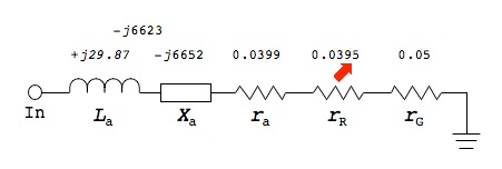
All values are in ohms. The first thing we notice is that the net reactance of −j6623 ohms is many orders of magnitude larger than the radiation resistance. Hence, virtually all of the RF input voltage will be dropped across the reactance and almost nothing will appear across rR, effectively preventing anything from being radiated from the antenna. And, excuse me for shouting: This explains why you can’t simply connect a wire to the plate of the output tube (or collector of the output transistor), and expect to get any range at all.
By comparison, a non-electrically small antenna would typically have a much smaller reactance (maybe tens of ohms off resonance, and essentially zero at resonance), and a much larger radiation resistance in the tens or hundreds of ohms, making it much easier to get the RF power radiated.
Fortunately, we can add a positive reactance in series with the antenna to cancel out the negative reactance. At 1000 kHz, an inductor of 1054 µH will have a reactance of j6623 ohms and will cancel out the net antenna reactance of −j6623. (A similar matching inductance is commonly seen with base loaded whip antennas for car mounted ham and citizen’s band use.)
We are now left with only the resistive components ra, rR, and rG (with a total equivalent antenna resistance of 0.1294 ohms). This is a huge improvement, but we see that the radiation resistance is about one third of the total equivalent antenna resistance. The power dissipated in a resistance is given by:
If we connect a 1 volt RF signal to the antenna input terminal (neglecting any source impedance for the moment), the total power dissipated in the antenna as both heat and radiated RF is 1V2/0.1294Ω = 7.73 watts. Looking at the voltages dropped across the individual resistances, there will be 0.308 volt across ra, 0.305 volt across rR, and 0.386 volt across rG. The radiated RF will be 0.3052/0.395 = 2.36 watts. The efficiency is then 2.36/7.73 = 31%. And this is an extremely optimistic value. We haven’t considered source impedance of the transmitter yet, and there are other stray losses that haven’t been mentioned. However, we can see that if we manage to cancel out the antenna reactance, then we at least have a chance of getting a better than insignificant fraction of the RF power radiated out of the antenna.
The following chart shows the theoretically correct value of series loading inductor for different antenna lengths and different frequencies. The curves assume an antenna conductor diameter of #12 AWG (2 mm). The conductor diameter affects the conductor inductance contribution to the overall antenna reactance which is relatively small over the frequency and antenna length ranges shown here. If the antenna conductor is thick enough not to break, for the given antenna length, then these curves will be sufficiently accurate.
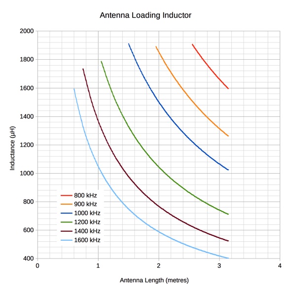
The curves begin to bend up sharply at the left side of the chart, as the required loading inductance rapidly increases. These inductance values—greater than about 1500 µH—are generally not practical, due to the tendency to self resonate at these operating frequencies. A curve for 600 kHz had also been generated, but even the longest legal antenna of 3 metres would require a higher than reasonable inductance value.
The preceding discussion was about a vertical monopole antenna. Achieving something like that in a home application, where vertical space is likely limited, will be difficult. In real life, the antenna may run vertically as it leaves the transmitter, but then may have to bend a few times to avoid obstructions, and possibly finish with part of it running horizontally. That is exactly the case with my own experimental antenna. So, how does this real life antenna compare to the vertical monopole? As it turns out, it compares reasonably well. Of course ‘reasonably’ is a subjective term. In my own application, the numbers are the same order of magnitude. For example, the vertical monopole has a calculated capacitive reactance of 6623 ohms which is equivalent to a capacitance of 24 pF at 1000 kHz. Measuring my own antenna the capacitance came out to be about 52 pF (the measurement explained below). This is more than double, but is also easily explained. The additional capacitance is due to proximity of the antenna to nearby metal objects as well as higher capacitance to ground due to a portion of the antenna which runs horizontally. A factor of two difference really isn’t so bad, especially when dealing with such small capacitance values. It’s not uncommon to have circuit stray capacitance values of 20 pF. It wasn’t practical to measure any other parameters, but considering that the capacitance was in the right ballpark, it indicates that the we are on the right track.
All of the small transmitters that I’ve built so far use a pentode vacuum tube as the output stage, with the output taken from the plate. The plate impedance of a pentode is extremely high, in the hundreds of kilohms. Similarly the collector of a bipolar transistor has a very high impedance. We then have the problem of matching a signal source with a very high impedance in kilohms to an antenna with a radiation resistance in milliohms. Obviously some sort of impedance matching network is required. Perhaps the most obvious choice would be a transformer to match the impedances. This is certainly one option, and this has been done in some low power transmitter projects, though it’s not a method that I’ve employed. Another approach is to use a T network or a Pi network. The first couple of transmitters that I built used a Pi network for antenna matching. The Pi network is shown here:

I made the Pi network highly adjustable by using variable capacitors and an inductor with multiple taps. The variable capacitor on the left (transmitter side) has a range of 35–350 pF. The capacitor on the right (antenna side) has a range of 10–100 pF. The inductor has a range of about 200 µH to 1200 µH. At the time that I built this matching network, I had not yet delved into the theory of small antennas, and did not have a feel for the magnitudes of the various parameters that I would be dealing with. Compounding this problem, there are a number of Pi filter calculators available on the Internet which simply do not work. Consequently I made everything adjustable so that I could find the best match between transmitter and antenna by means of knob twisting. This circuit will match a wide variety of antennas over a wide frequency range, but it turns out to be both more complex than necessary, and not as efficient as other matching methods. However, one clear advantage of the Pi network is that, besides providing an impedance match, it is also a low pass filter, that minimizes transmitter harmonics from getting to the antenna and being radiated, a very useful benefit especially for poorly designed transmitters. Harmonics are an especially serious consideration when using an electrically small antenna. The antenna’s efficiency improves dramatically as frequency increases, and if harmonics are present, the antenna can easily radiate more more energy in harmonics than at the fundamental frequency. In fact, when tuning one of these antennas, it’s important to start with the matching network set to its lowest frequency and then slowly increase the frequency until a peak occurs in radiated power. Starting at the high frequency end will almost certainly lead to the antenna being peaked on a harmonic.
Referring back to the equivalent antenna model, the following diagram shows the equivalent circuit with a matching reactance Xm added to null out the antenna reactance Xa.
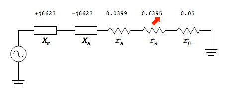
The RF signal source (the transmitter proper) is shown on the left as an ideal voltage source. Voltage sources are normally considered to be zero (or at least very low) impedance, and as such this is a good configuration, since the high reactance has been cancelled and the only remaining impedances are ra, rR and rG which add up to only 0.1294 ohms in this example, giving good power transfer to the antenna. But in reality, the RF signal source, in the case of a vacuum tube plate or transistor collector is, instead, a very high impedance which could be considered a current source rather than a voltage source. Replacing the voltage source with a current source in the above diagram will give a very bad impedance match. However, it is possible to connect the high impedance RF current source into the circuit in a different position—at a high impedance node—to give a much better match. In the following diagram the high impedance RF source (shown as a current source) is connected to the junction between Xm and Xa.
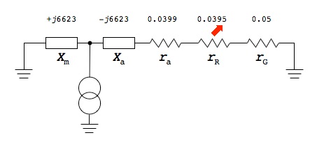
To demonstrate that this is a much higher impedance node, we can analyze it as follows. Since the resistive components ra, rR and rG are very much smaller than Xa and Xm, we will neglect them for the moment, and assume the total impedance to the right of the current source to be −j6623 ohms. Therefore, we see a parallel combination of Xm and Xa from the RF current source to ground. The formula for two impedances (reactances) in parallel is:
But we see that because Xm and Xa are equal in magnitude, but opposite in sign, the denominator tends towards zero, and the net impedance therefore tends towards infinity. Thus, this is a very high impedance node in the antenna circuit, and a suitable point for connecting a high impedance source. Now we must translate this back into a real circuit. This turns out to be very simple, as the following diagram shows.
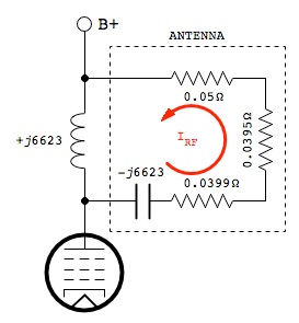
Bear in mind that as far as RF is concerned, B+ and ground are the same thing, so we show the ground return end of the antenna equivalent circuit connected to B+ to illustrate that we have a parallel LC tank. At resonance, a parallel LC tank has very high impedance, making it a good match to the high plate impedance of the output tube, and at the same time it has high circulating current (IRF in the diagram). This high circulating current through the antenna matches the low radiation resistance of the antenna.
In practice, we won’t be able to find a fixed value inductor that is the exact value necessary to match the antenna. And, for proper matching it’s critical to have the exact value. Just a small percentage difference will take the circuit far enough off resonance to significantly reduce power output. And indeed, we won’t be able to predict the exact value beforehand anyway, because there will be enough variations in the actual antenna configuration to make this impossible. Therefore, a variable inductor, if one can be found, is the ideal solution for matching this antenna. Variable inductors in the 500–1200 µH range were reasonably easy to find many years ago, but are very rare today, and the few that are available usually have too narrow an adjustment range for them to be useful. To solve this problem, one can sometimes find a smaller value variable inductor, and connect it in series with an additional fixed value inductor to bring the overall inductance into the correct adjustment range. But in many cases another solution is needed.
While not quite as efficient, a fixed value inductor of a value slightly lower than that required for resonance can be used, along with a small variable capacitor added in parallel as shown below. (The proper value inductor can be determined from the Antenna Loading Inductor chart above.)
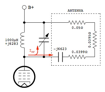
It’s not as efficient, because the tank current is now divided between the trimmer capacitor and the antenna (see red IRF arrows), in proportion to their capacitances: more current will flow through the higher capacitance. And it is only the portion of current that goes to the antenna that results in radiated energy. But, as long as the required trimmer capacitance is very small compared to the antenna capacitance then the loss of efficiency can still be acceptable.
For example, a 1000 µH (j6283 ohms) fixed value inductor could be used instead of the exact 1054 µH value in our example, and then a trimmer capacitor added in parallel. In this case, because the fixed value is so close to the predicted value, we need only a very small capacitance (1.3 pF) giving a reactance of −j122389 ohms in parallel with the antenna reactance of −j6623 ohms to match the inductive reactance of j6283 ohms. However, things can rapidly deteriorate. If we had only a 470 µH (j2953 ohms) inductor available we would need 30 pF of additional capacitance to resonate, and now almost half the current would be bypassed through the trimmer rather than going to the antenna. So, the general rule is to use the largest value inductor possible, and just enough capacitance to resonate the tank, in order to get the maximum radiated power.
A practical circuit is shown below.
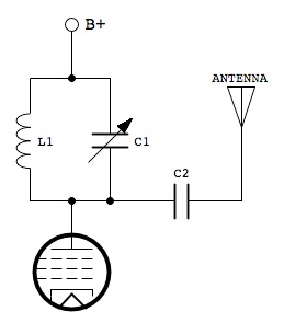
It can be seen that a second capacitor C2 has been added. This is for safety reasons. Its purpose is to isolate the high DC plate voltage from the antenna. Its value should be much higher than the antenna and trimmer capacitance so that it has minimal effect on resonance. A value of 0.05 µF is suitable. A further rearrangement of the antenna circuit is recommended in some cases, again for safety reasons. Sometimes a metal frame variable capacitor is employed for C1. Since the rotors of these capacitors are connected to the frame, it is necessary to isolate the frame from ground by mounting it on insulated standoffs, and ensuring that an insulated knob is used on the adjustment shaft. By rearranging the antenna circuit as shown below, this problem is averted.
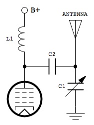
The component values are the same as before, but it can be seen that the variable capacitor C1 now has one side (the frame) grounded, making insulated standoffs unnecessary, and the other side is also isolated from B+ by means of C2. Since B+ and ground are equivalent as far as RF is concerned, this is effectively the same parallel LC tank circuit as before, except that the high DC voltage components are removed from C1 and the antenna.
I decided to perform some experiments to see how different values of inductance and capacitance in the parallel LC tank matching network would affect the amount of RF output.
For my first test, I wanted to use inductance only with no parallel capacitance since, according to the preceding theory, it should give the most radiated power. I had available a variable inductor with an adjustment range of 40–120 µH, which would not be enough by itself to match the antenna at 1000 kHz. So, I tried different fixed value inductors in series with the variable one until there was sufficient inductance to tune the antenna to resonance.
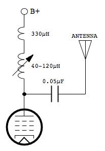
With this arrangement, I was able to peak the antenna with no additional parallel capacitance, and so all circulating tank current is flowing through the antenna. This should give the most efficient coupling to the antenna.
I set up the transmitter as shown in the circuit above, using a fixed inductance of 330 in series with the 40–120 µH variable inductor, and placed a passive signal strength meter a fixed distance from the antenna (see photo at top of this page). For the first test, the inductance was adjusted for peak output, which occurred when the total inductance was 446 µH. (This differs from the earlier calculations that predicted a required inductance of 1054 µH, but is explained by additional stray antenna capacitance.) The signal strength on the meter was then recorded.
For the next test, I removed the 330 µH series inductor, so that only the variable inductor was in the circuit. I had, by this time, estimated that the antenna capacitance was roughly 50 pF and so it would require an additional 220 pF of parallel capacitance to peak the antenna with the variable inductor set near its maximum inductance. I connected the 220 pF capacitor in parallel with the variable inductor and then re-peaked the antenna, again recording the signal strength.
I repeated the experiment with different fixed value capacitors, and recording the signal strength with the variable inductor adjusted for the best peak. The results are in the table below:

L is the actual measured value of inductance when the circuit was at resonance.
C-net is the calculated total tank capacitance based on the measured inductance using the standard LC resonance formula at 1000 kHz.
C-parallel is the measured value of the fixed value parallel capacitor that was added to the circuit (nominal values were 220, 270, 330 and 560 pF respectively).
C-antenna is the antenna capacitance calculated by subtracting C-parallel from C-net. The average of these comes out to 52 pF. So, the antenna capacitance is therefore deemed to be 52 pF.
Recorded signal strength is as read from the signal strength meter which has a scale of 0–10. I have no idea whether this 0–10 scale is supposed to be linear. I suspect not. So, while we can say that 7 is definitely better than 3.5, we can’t really say that a value of 7 is twice as good as value of 3.5. (It may be more than twice as good, or it may not be quite twice as good.)
It can be seen that the experimental results confirm the theory. The maximum signal strength was highest when inductance alone was used, forcing all resonant current through the antenna. Also as predicted, when parallel capacitance was added in order to peak the antenna, the smallest capacitance gave the most output signal strength.
After performing these tests, I was curious how the previously mentioned pi network would compare with the parallel LC matching network.
So, I repeated the experiment one more time using the pi network. In this case the variable capacitor on the right hand side of the pi network was omitted because it would be effectively in parallel with the antenna capacitance and would lead to the same current splitting problem that occurs with the added capacitor in the parallel LC tank network.
Adjusting the pi network for maximum output, the signal strength reading was only 1.4—the worst of any of the experimental arrangements. Though, as mentioned earlier, the pi network would be the better choice for minimizing harmonic radiation.
More recently, I've been looking at the use of a loop antenna as an alternative to a monopole antenna. Loops are more compact, less likely to be tripped over, and I've found that they may work better at lower transmitting frequencies (1000 kHz and lower), where the monopole antenna is more difficult to match. It's just a matter of disconnecting the monopole antenna, and replacing L1 with a loop antenna, preferably having an inductance in the range of 200 to 250 µH, which is typical for the loop antennas attached to the back of tube radio receivers from the late 1940's to the end of the tube radio era. In fact, for my first experiment I used the loop antenna from an early 1950's General Electric radio. Its inductance measured 220 µH and I was able to tune it to any frequency on the MW band using the tuning capacitor from a similar radio. The antenna circuit is as follows:
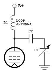
One caution however: Note that the entire loop is at B+ potential. So, it must be well insulated and physically protected from damage (and children and pets that like to chew on things).
The loop transmitting antenna was directional when close to the receiver (less than 2 metres away), as one might expect. However, unexpectedly, if the transmitting antenna was rotated to minimize the signal at the receiver, then the receiver's loop antenna could be rotated to regain a strong signal. This was a bit of a surprise, but is likely a quirk of operating in the near field regime. I also found that separating the transmitter and receiver by a greater distance (5 metres apart), the transmitting antenna appeared to become non-directional. Rotating it had no effect on the received signal. However, the receiver's loop antenna was directional at this greater distance and acted in the expected manner, giving best reception when aimed at the transmitter. These results were from a limited amount of testing, and further work needs to be done.
The simplest and most efficient matching network for an electrically small broadcast band antenna is nothing more than a properly sized plate inductor, or parallel inductor/capacitor tank with the smallest possible capacitance.
It was pointed out that because of the extremely low radiation resistance of the antenna, the other losses must be kept down to the same order of magnitude in order to get any reasonable amount of RF emission.
No mention has been made of the resistive component of the matching inductor L1. It should, of course be as low as possible because it ends up being in series with the other losses. Commercially available inductors will have their DC resistance specified. The AC resistance will vary with frequency, but the Q values will be specified. All other things being equal, inductors with highest Q should be chosen.
For the antenna itself, the largest practical diameter conductor should be chosen to minimize antenna resistive losses. Copper is the best conductor material because of its low resistivity.
Back to:
Radio Theory
Projects
Home
This page last updated: February 7, 2023
Copyright 2010, 2023 Robert Weaver