Crystal sets–totally passive receivers without any amplification–have been popular for many
years. The vast majority of them are designed and built for the
Medium Wave band, 530 to 1700 kHz. However, there have also been some
built for the shortwave bands, and occasionally some for the FM band
(88 to 108 MHz).
Having
several local powerful FM stations, I'd occasionally noticed that I
was picking up FM on a medium wave crystal set. Considering that
there was a strong enough signal to receive FM when it wasn't wanted,
it should be possible to build a receiver to pick up the signal
intentionally.
Most FM
crystal sets use slope detection. That is, they are tuned slightly
off the centre frequency of the station, and as the frequency
modulated carrier moves in and out of the receiver's resonant
frequency, an audio signal approximating the original modulation is
produced. True FM detection requires a frequency discriminator
circuit, and the complexity generally makes it unsuitable for a
passive receiver. I'm only aware of one such project. It was designed
and built by Edward Richley, and was written up in the
Xtal Set Society Newsletter, January and March 1996.
In order to achieve the high Q required, the circuit used a coaxial resonator
constructed from 2 inch copper pipe. It was ingenious in that, while
most FM discriminators have two tuned circuits, this one only
required a single tuned circuit. This was an important feature,
because trying to adjust two tuned circuits when tuning to different
stations, would be extremely difficult, if not impossible.
I've
redrawn the Richley circuit here:
A very brief description of the circuit follows. For a more thorough
discussion, please refer to the original newsletter articles.
As described in the diagram notes, the resonator is constructed from a
two foot piece of 2 inch diameter copper pipe, with a centre
conductor of 1/2 inch copper pipe. The resonator is designed for an
unloaded Q of 2000, and a loaded Q of about 500, which is required
for acceptable selectivity. FM channel bandwidth is 200 kHz, or 0.2
MHz. Therefore, at a frequency of 100 MHz, required Q will be
100/0.2=500.
Transformers T1, T2, and T3 are made from standard 300:75 ohm baluns which are
included in the kit of parts that come with virtually every new
television or radio. T1 is used unmodified. T2 is rewound as 1:3
autotransformer. T3 has a two turn primary and a two turn secondary.
Transformer T1 converts the incoming unbalanced signal to a balanced
signal which then feeds T2 and T3. The secondary of T3 is loosely
coupled via the 8 pF capacitors to the resonator coupling
loops, which develop a 90° phase shifted signal due to the normal
behaviour of a coupled circuit at resonance. The secondary of T2 is
connected to the common point between the diodes. This signal is 180°
out of phase with the incoming RF. Hence, there are quadrature
signals applied across the diodes which act as a synchronous
detector. As the frequency modulated radio carrier moves above and
below the resonant frequency, the phase shift varies above and below
90°. The detector converts this phase shift into an audio frequency
signal which matches the original audio source.
Initially, I planned to build a copy of this receiver, but after doing a bit of
research, I concluded that a helical resonator would be more
practical at these frequencies. My new plan was to duplicate this
circuit, except that I would substitute a helical resonator for the
coaxial resonator.
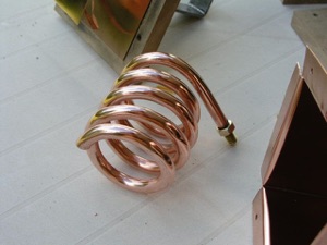
The first step then was to design a helical resonator with an unloaded Q
of 2000 at a resonant frequency of 110 MHz, the top of the FM band.
Using standard helical resonator design formula, the resulting resonator
has an inner coil constructed from 4.3 turns of 9.5mm (3/8")
copper tubing. Coil outside diameter is 65mm (2.6"), and coil
length is 84mm (3.3").
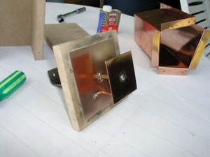
The shield is constructed from copper sheet, and is 84mm (3.3")
square by 200mm (8") long. It is housed inside a wood enclosure
for rigidity. The shield is about 2" longer than required to
allow room for coupling loops at the bottom, and for a tuning
assembly at the top. The photo to the right shows the shield parts prior to assembly.
The tuning
mechanism is a small plate attached to a length of brass tubing which
runs through the end cap. The rod is moved in and out by means of a
screw. This changes the fringing capacitance at the open end of the
coil. The closer the plate is to the coil, the lower the resonant
frequency. The photo to the right shows the top cap with tuning mechanism
assembled. The tubing has a square cross section to prevent the
assembly from turning. It slides inside a slightly larger piece of square tubing. This type of tubing
is available at hobby shops and comes in a range of sizes suitable
for close sliding fits.
The coil and the inside of the shield were
polished to remove oxidization, and hence maximize Q. The partially
assembled resonator is shown in the next two photos. The photo on the
left is of the top end, and the photo on the right is of the bottom
end.
The next photo shows the top cap installed and the exterior part of the
tuning mechanism:
I decided that for initial testing, it would be best to keep things
simple and use a slope detector circuit. This is shown in the
following schematic:
The 27 µH choke and 150 pF cap are a low pass filter to trap out a local
high powered AM station that was causing some interference problems.
For a diode, I used a 1N34A initially, but found another unknown type
in my parts box which worked slightly better. It may in fact also be
a 1N34A from a different manufacturer. The detector and coupling
loops were built on a small circuit board and mounted on a block of
wood so that the assembly could be repositioned easily to obtain the
best performance. The assembly is shown below.
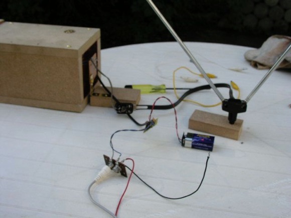
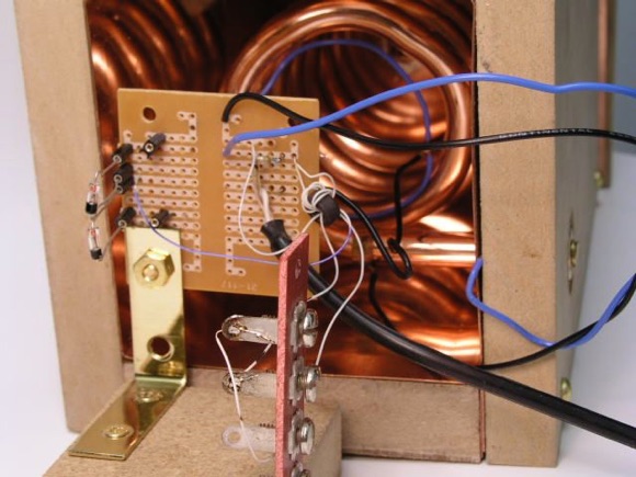
The RF and detector coupling loops are blue hook-up wire. The little
postage stamp sized circuit board is a low power headphone amplifier
which was used in conjunction with my relatively insensitive
headphones to make testing a bit more painless. The initial working
set-up is shown below:
Reception was fairly good. The signal was weak using my piezo phones without
any amplification. So, I connected in the headphone amplifier, and
did all the remaining testing with it. Selectivity was very good.
However, I don't have any easy means to measure the Q. I found that I
could easily pick either side of a station's centre frequency for
detection, and if I tuned dead centre, the signal became very
distorted. That leads me to believe that the Q is very high. I
couldn't get that kind of precision with earlier experimental sets
which used a coil/capacitor tuned circuit.
So with
that bit of success, I started thinking about making a true
discriminator. As mentioned above, I had intended to duplicate Ed
Richley's circuit except that the coaxial resonator would be replaced
with the helical one. However, after reviewing the original circuit,
I concluded that two of the transformers could be eliminated. The
first transformer is a balun to convert from an unbalanced RF signal
from the antenna to a balanced one. Since I intended to use a dipole
antenna, this was unnecessary.
Rather
than excite the resonator via coupling loops through the small
capacitors, I decided to drive the resonator directly at a tap near
the ground end of the resonator coil. This eliminated the need for
the balanced secondary winding on T3.
I decided
that I could combine T2 and T3 into a single transformer. I had
disassembled several baluns and found some to have two-hole cores and
some were simple toroids. I used the toroid from one of these and
wound a 4-turn primary, and 4-turn secondary. The secondary has a tap
after the first turn which is grounded. The schematic follows:
The secondary arrangement still gives the same 3:1 power ratio between
the diodes and the resonator excitation, but the circuit is much
simpler. The revised coupler/detector board is shown below:
The black wire with the brass clip is for connecting to a tap on the
resonator coil. I made it this way so that I could quickly try
different positions. Optimum turns out to be about 40mm (1.5")
from ground.
The pickup
loop is the single loop of blue wire with the audio output tap at the
halfway position (black wire).
Diodes are socket mounted so that different ones may be tried without fuss. I
didn't put in an AM trap this time, because the circuit arrangement
is not conducive to AM pickup, since the diodes are essentially
shorted at MW frequencies by the pickup loop.
Here's a
brief description of how the circuit works:
Input
transformer T1 splits the incoming RF (untuned) into two signals 180
degrees out of phase with reference to ground. The low level side
goes to the resonator and the high level side goes to the common
point of the diodes. The voltage induced by the resonator into the
pickup loop will be 90 degrees out of phase with the the input
signal. This is the nature of a loosely coupled tuned circuit at
resonance. The phase of the signal on the pickup coil will vary on
either side of 90 degrees as the carrier is frequency modulated. The
"90 degree" signal is applied to the outside ends of the
diodes while the 180 degree signal is applied to the diode common
point which then act as a quadrature detector. Hence it is
essentially the same mode of operation as Richley's original circuit.
The
following photo shows the discriminator assembly in position:
Now, with everything connected up, and after finding the best position for
the pickup coil I found that the discriminator appears to be working
correctly. Tuning is sharper, and there are no double slopes to
select as I could previously. In fact tuning this receiver has very
much the same feel as tuning a commercially made FM receiver. Audio
level has increased significantly too. This is something I had been
wondering about. I was concerned that a true discriminator might be
less sensitive than a slope detector, but it appears not to be the
case.
2010-11-28 Update:
Since the original material
first appeared on this page, I've continued to tinker with this
circuit, resulting in several incremental improvements. Although the
improvements came in many small increments, the cumulative result is
that this is now a very good performing receiver. Improvements listed
in order of importance (most important first) are:
Changing
the detector diodes to Avago HSMS-2850;
Changing
the turns ratio on the RF input transformer;
Getting
a good set of sound powered headphones;
Permanently
mounting the detector loop;
Finding
a good antenna location;
Shortening
the resonator helix.
Diodes
The Avago (formerly Agilent) HSMS-2850 diodes are rather odd ones.
I had purchased these along with a number of other different types of
detector diodes, more or less at random, to test their effectiveness.
These particular diodes were described as "zero bias" which
made them too intriguing to pass up. When they arrived, I set them
aside and didn't think about them again until I ran across
this page on Dick Kleijer's site.
He had also built an FM crystal set
and had tested a number of different diodes. Among them were the
HSMS-2850's which turned out to be his best performers. I dug through
my diode assortment and confirmed that they were the same ones I had.
These are surface mount, and so I had to construct a small printed
circuit adapter board. Otherwise, I would have tried them much
sooner. When I tried them, there was a considerable improvement in
performance. I mentioned that these diodes are odd ones. They have a
very low R0 (zero crossing resistance) of about 5000 ohms (many
thanks to Mike Tuggle who measured them for me). Coincidentally, this
is about the same R0 as a galena detector. The low R0 would normally
make them a bad choice as a crystal set detector (galena aficionados
notwithstanding). However, it appears that this particular resonator
circuit has a very low resonant RF output resistance, which turns out
to be a good match to the diodes. For more info on this, see
Ben Tongue's site.
This low RF resistance has another
consequence which is discussed below.
In addition to the above
mentioned diodes, I also recently tested Sanyo 1SS351 diodes. These
are a surface mount type, with two diodes in a single package, and
while not quite as sensitive as the HSMS-2850's they are
significantly better than any of the germaniums or other Schottkys
that I've tested. I also tried paralleling two of these, and got a
further improvement in performance. In a listening test (which was
completely subjective) I found it difficult to tell much difference
between the parallel 1SS351's and the singleHSMS-2850's.
RF Input Transformer
Getting the best turns ratio for the RF input transformer was an
iterative procedure which also affected the optimum input tap
position on the resonator. The schematic appearing earlier on this
page shows a primary with 4 turns, and a secondary with 4 turns, with
a grounded tap at 1 turn. After much experimentation (and wire
breakage), I currently have a primary with 6 turns, and a secondary
with 8 turns, with the grounded tap again at 1 turn. This is the
current schematic:
I might have arrived at this turns ratio a bit sooner if I hadn't made
a bit of a blunder, confusing a dipole antenna with a folded dipole
antenna, and thinking my antenna impedance was 300 ohms when in fact
it is 75 ohms. (You may pick up on this goof in the earlier text of
this page, which I haven't corrected yet.) I'm not yet at the point
where I will claim this transformer configuration to be optimum, but
it is much improved over what I had before.
Another addition is the 27µH
choke connected between the centre tap on the detector loop and the
phones. This seems to help isolate the audio wiring from the RF part
the circuit, and vice versa. This improvement is subjective at this
point (it seems to increase volume), but regardless, it doesn't
appear to be a bad idea.
There were a few other changes
made to the circuit as well, but in the end, except for the diodes,
the revised RF transformer windings, and the addition of the 27µH
choke, the other changes resulted in negligible improvements. Hence,
they were dropped.
While
on the subject of the schematic diagram, alert readers will note the
apparent short circuit at audio frequencies if the diodes happen to
be conducting. The consequence of this is that when receiving a very
strong signal, there is an upper limit to how much audio the detector
will produce. My earlier circuit simulation verified this, but I
haven't yet encountered a real life signal strong enough to hit this
limit. However, I have allowed for circuit modifications should this ever become a
problem. It would involve the addition of a resistive or reactive
component (Z1) between the diodes as shown in the diagram here. The
circuit model used in the simulation does not yet have sufficiently
accurate parameters for the diodes or other components, to give a
good idea what values to use for Z1 or the coupling capacitors. My
circuit board has several strategically located jumper plugs to allow
for this future addition without the need for any soldering or
de-soldering.
Sound Powered Phones
There's not much I can say about sound powered phones other than:
If you're serious about crystal radios, eventually you'll have to get
a pair. There is nothing else that compares in sensitivity. Piezo
phones are not bad if you have nothing else available, but simply
don't compare to sound powered phones . I was lucky enough to get a
pair of Western Electric SP phones (thanks to Darryl Boyd), and with
the other improvements that were made in the receiver, there is no
longer any need for an amplifier, not even for testing purposes.
The Western Electric phones
(model D173014) have an impedance of about 600 ohms per element, and
I have them wired in series for a total impedance of 1200 ohms. This
turns out to be such a good match for the low impedance detector,
that I have not found any advantage to using an audio matching
transformer. Originally, I tested these with a Bogen T725 transformer
wired as an autotransformer. The best transformer configurations were
the 2:1 and 4:1 ratios. However, I couldn't honestly detect any
improvement over the direct connection using no transformer at all. I
did notice a slight difference in frequency response (better bass
with the transformer), but no net improvement in volume using the
transformer. I'm guessing that the optimum impedance would be
somewhere around 2400 to 3000 ohms, but the transformer's insertion
loss probably negated any benefits from the better impedance match.
Detector Loop Mounting
Originally, as shown in the early photos above, I mounted the
diodes and detector loop on a separate moveable base. Once I'd
determined the optimum position for the loop, I mounted it
permanently through the side of the enclosure. This eliminated quite
a bit of excess wire which is never good to have when dealing with
VHF. The RF transformer and diodes are now mounted on the side of the
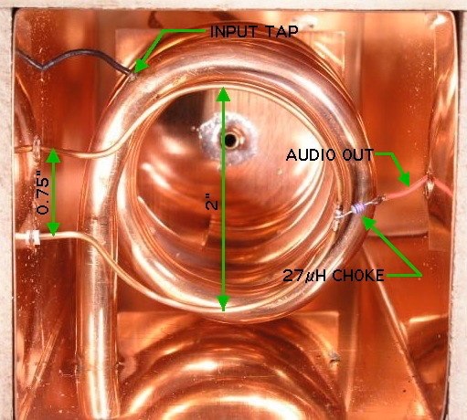
enclosure where the leads come through. Here is a detail of how the
detector mounts:
The detector loop is 50 mm (2") diameter #14 AWG (1.6 mm) copper
wire, which is stiff enough to maintain optimum shape and position,
once those have been determined. It is a friction fit through the
side of the enclosure. Both leads are insulated where they pass
through the shield.
The detector loop could mount
through any of the four sides of the shield. However I chose the
arrangement shown here, where both ends of the loop cross the ground
end of the helix at 90°. It's my belief that this would minimize any
possible unbalance in the loop due to ground capacitance effects.
What isn't shown in the photo,
is the separation between the detector loop and the bottom of
resonator helix. The distance is approximately 16 mm (5/8"). The
loop has a bit of a twist in it, to follow the pitch of the helix, so
that separation is a fairly constant 16 mm at all points, except
where it bends around the ground end of the helix. Audio is taken off
at the middle of the loop through the 27µH choke. The input tap
(black wire) is connected to the resonator helix about 75 mm (3")
from the grounded end.
Antenna Location
Unfortunately, antenna location is much more critical when dealing
with VHF than when dealing with medium wave. A change in position of
less than a metre can drastically affect reception. Initially, I
found that to receive some stations, the antenna would have to be in
one position, and to receive other stations, the antenna would have
to be moved somewhere else. In all cases the antenna would have to be
rotated to get the strongest signal.
My antenna is a simple set of
rabbit ears (dipole) that was supplied with some long forgotten
television receiver. I have it mounted on a camera tripod with a pan
head, making it easy to rotate.
Currently, it sits in one
corner of my house where I find that it gives good reception for all
of my local FM stations (except one; more on that below). I have no
explanation for why this particular location is best. No doubt, there
are many complicated factors. However, I do note that this is in a
far corner of my house which likely has the least amount of
electrical wiring in the walls and ceiling.
Resonator Helix Length
Originally the helix was 4.3 turns of tubing. According to my
design calculations this should have given a resonant frequency of
about 110 MHz, just above the top of the FM band. In practice, it
gave a resonant frequency of just a bit over 103 MHz. I expect this
is mainly because I wasn't able to make the helix diameter exactly as
designed.
The resonant frequency is also
affected by fringing capacitance between the ungrounded end of the
helix and the outer shield. If the helix is not perfectly centred in
the shield (particularly the ungrounded end) the fringing capacitance
will be higher and the resonant frequency will be lower. The resonant
frequency can often be increased slightly by adjusting the position
of the helix (ie., making sure it's exactly centred). However I
wasn't able to increase the resonance enough, using this method. So,
I trimmed pieces off the end of the helix until the resonance
increased to an acceptable value.
After
trimming, the helix was stretched out lengthwise to return the
overall length to the design value of 84mm (3.3").
Currently, the the helix is
3.75 turns, and it tunes up to 106.3 MHz which covers all of the FM
stations in my area, but not quite the whole FM band.
Performance
Shortly after building the phase discriminator version of the
detector circuit, I was asked–quite legitimately–whether I was
certain that the circuit was behaving as a proper phase detector, and
not just an oddly configured slope detector. So, it was quite
important that I verify its operation. Previously, I'd run a circuit
simulation which indicated it would work. Then subsequently, I put a
digital voltmeter on the audio output and verified that as an
unmodulated carrier was slowly and manually swept across the resonant
frequency of the receiver, the output went negative, crossed through
zero, became positive and then dropped to zero again. But that's a
far cry from actually seeing a decent response curve on a scope.
Unfortunately, I don't have a
VHF signal generator which can be suitably frequency modulated.
However, I do have a cheap FM modulator (intended for playing
portable music players through a car's FM radio). It uses a Rohm
BA1404 FM modulator IC. The RF output is tied back into the 12V power
cable which plugs into the car's cigar lighter. This was not suitable
for providing a reliable and consistent signal to the receiver. So, I
had to perform some surgery. Thanks to an online data sheet for the
BA1404, I was able to locate the RF output (pin 7, for anyone
interested), and connect a separate RF output lead.
Once I managed to separate the
RF output, I got a nice clean signal. My audio sweep source is a sine
wave from an audio generator. The only remaining complication was
that the FM modulation was slightly out of phase relative to the
input audio signal. So, I had to build an adjustable phase shift
circuit to go between the audio generator and the scope X-input. Once
it was adjusted properly, the waveform cleaned up very nicely, and I
was quite thrilled to see a fairly good S-shaped discriminator
response curve which is shown here:
This is the actual DC response of the detector with an input FM signal of
about 100 MHz. Mid position on the graticule is 0 Volts DC. Some
asymmetry can be seen in the response curve; the skirt on the right
tapers off much more gradually than that on the left. At some point I
will probably investigate why this is happening, though I'm not too
concerned about it. The flat section on the left is an artifact of
the FM modulator. All things considered, I'm quite happy with the
results.
Unfortunately, because the
modulator is uncalibrated, I'm unable to say just what the actual
bandwidth is. I hope to address this in the future.
As a side note, it can be seen
that the trace is somewhat fuzzy. This is because there is a
superimposed 19 kHz stereo pilot tone which is produced by the FM
modulator. This had me baffled for a while until it dawned on
me what it was. By adjusting the audio generator frequency, the 19
kHz signal can be made almost stationary, but still moves too fast
for the camera to catch it.
The test set-up, used to
generate the above response curve, is shown here:
Listening Test
I have twelve local FM stations (within approx. 30 km). With this
receiver I can clearly hear all except for two of them. Of those two,
the first (91.7 MHz) seems to be temporarily off the air (although I
can pick up its unmodulated carrier on other receivers). The second
(100.3 MHz) is so weak that I can barely pick it up on a regular FM
receiver, and even then, it is buried in noise and is barely
intelligible.
So, I wasn't too upset about not picking it
up on the crystal set.
The ten local FM stations,
which I can hear clearly, range in power from 1300 Watts to 100,000
Watts. All of them can be heard at pleasant volume in a reasonably
quiet room. The 1300 Watt station is one of the loudest. However, its
transmitter is probably closer to my listening location than the
others. The receiver is selective enough that there is absolutely no
overlap in stations. Audio quality is very good with the sound
powered phones.
Four of the stations are strong
enough that they can be heard fairly well with Sony MDR-W08 Sport
Walkman phones when properly matched with a Bogen T725 transformer.
Although the volume was considerably lower than with the sound
powered phones, it was still quite intelligible.
Here
is an audio clip tuning through the ten local stations starting
at 88.7 MHz and ending at 105.5 MHz, which gives a general idea of
the audio quality. File size is 1.6 MB. It was created by connecting
the crystal set audio output through a simple RC de-emphasis filter,
into a microphone preamp and then into the audio input of my computer
running Audacity 1.25 software. The audio is exactly as recorded with
no editing or other processing. You will notice that the sound
quality changes rather erratically during tuning. This is due to
backlash in the tuning mechanism (particularly troublesome at the
bottom of the band), and simultaneous adjustment of antenna
direction.
Demo Video Clip
(Added March 2023)
Below is a video that I uploaded to Youtube many years ago, and which they have since deleted.
I recently found it again in some old backups, and have now converted it to mp4 format
so that it should be playable on any computer.
Please be warned (especially if using headphones) that there is an increase in audio
level after 00:01:40. So, be prepared to turn down the volume when you get to that point.
(I will try to edit the audio track to adjust the levels, once I figure out how to do it, and then re-upload.)
More to Come
While this project is close to being complete, a few things remain
to be done.
Firstly, the tuning mechanism
is very non linear. Tuning at the low end of the band is very touchy,
and backlash in the adjusting screw makes tuning these stations a bit
frustrating. You can see that in the above video, near the end, when
I'm trying to tune a station at 88.7 MHz.
I'm currently looking at an alternative tuning mechanism
which should result in more linear tuning.
Secondly, I would like to test
the receiver with a good quality outdoor FM antenna.
Finally, I need to rebuild the enclosure to make it more presentable.
Construction Data Summary (as of 2010-11-06)
Since a number of the circuit parameters have changed over the
course experimentation, and the numbers are scattered around this
page, I've consolidated the pertinent information into the following
summary:
Resonator
Helix
conductor: 9.5 mm (3/8") diameter copper tubing;
Helix
outer diameter: 65 mm (2.6")
Helix
length: 84 mm (3.3")
Helix
number of turns: 3.75
Helix
input tap position: 75 mm (3") from ground end of helix
Shield
material: 16 oz. copper flashing; 0.56 mm (0.022") actual
thickness
Shield
width: 84x84 mm (3.3" x 3.3")
Shield
length: 200 mm (8")
Distance
- helix mounting hole centre to bottom edge of shield: 50 mm (2")
Detector Loop
Material:
#14 AWG (1.6 mm) bare copper wire
Diameter:
50 mm (2")
Spacing
from helix: 16 mm (5/8")
Estimated
detector output impedance: 2400 to 3000 ohms
RF Input Transformer
Core
Type: Ferrite toroid
Core
Material: Unknown ferrite mix, but presumably suitable for VHF
broadband transformer use. Mine was salvaged from a TV 300-75 ohm balun


 problem. It would involve the addition of a resistive or reactive
component (Z1) between the diodes as shown in the diagram here. The
circuit model used in the simulation does not yet have sufficiently
accurate parameters for the diodes or other components, to give a
good idea what values to use for Z1 or the coupling capacitors. My
circuit board has several strategically located jumper plugs to allow
for this future addition without the need for any soldering or
de-soldering.
problem. It would involve the addition of a resistive or reactive
component (Z1) between the diodes as shown in the diagram here. The
circuit model used in the simulation does not yet have sufficiently
accurate parameters for the diodes or other components, to give a
good idea what values to use for Z1 or the coupling capacitors. My
circuit board has several strategically located jumper plugs to allow
for this future addition without the need for any soldering or
de-soldering.