
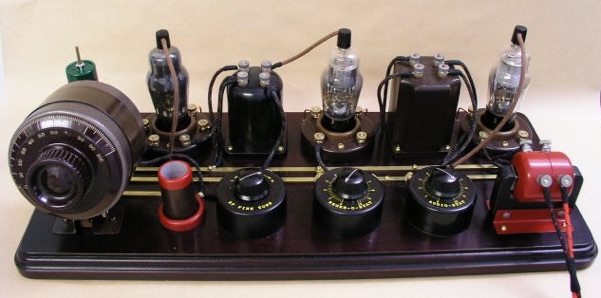
The visual style of this receiver was inspired by the 1920’s Atwater Kent Model 10, which had all of the components mounted on a flat wooden baseplate, and had no front panel. The present receiver is a bit of an anachronism, because these tubes were not developed until at least 10 years after the Atwater Kent model 10 was built, and construction methods were radically different by that time. However, I didn’t let that stop me. The above picture shows the front view, and the following picture is the rear view:

For the construction, I either needed to find old components, or else make new components look old. Since I already had the circuit working very well, I didn’t want to start changing components. So instead, I decided to make vintage style housings for the various parts.
The materials used for the component housings were various pipe fittings of PVC or ABS plastic, and MDF (medium density fibreboard). While MDF is not generally appreciated by woodworking purists, I required a sheet material available in different thicknesses that is easily machinable, and has no grain marks, as the intent is to make the final result appear to be made of bakelite. Machinable plastics such as Delrin are available, but they are expensive, and offer little advantage over MDF. After sealing, and given a coat of dark brown spray paint, MDF looks very much like bakelite.
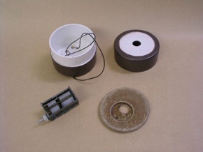
Starting with the tuning capacitor, the various components are shown here:


I used a very nice quality Unitra brand dual gang variable capacitor, made in Poland, and two 3.5” diameter PVC pipe caps. Of all the components, this required the most precision, because the tuning shaft had to be exactly centred in the pipe cap, but there were no obvious means for locating the capacitor mounting holes relative to the centre, except by very careful measurement with vernier calipers. To make things a bit easier, I transferred the measurements to a paper pattern, and when I was satisfied that it was accurate, I used it to make a round MDF adapter plate that fit snugly inside the pipe cap, and then mounted the capacitor on the plate.
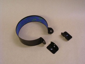
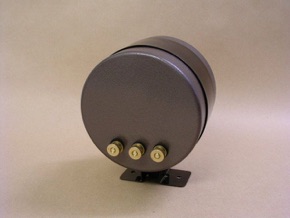
The mounting bracket is made from a strip of sheet metal, bent to shape, and finished with dark brown spray enamel. The PVC pipe caps were painted with brown hammer tone spray paint.
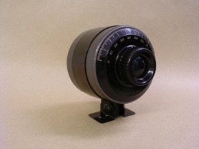
The last two pictures show the front and rear views of the completed tuning capacitor assembly. The knob is an original Atwater Kent knob made in the 1920’s. It is the oldest genuine part in this receiver. Circuit connections are by means of brass thumb nut terminals on the rear.
The audio interstage transformer housing is modelled after a Fada model 171-A transformer. Below, the picture on the left is a genuine Fada transformer, and the one on the right is my reproduction.
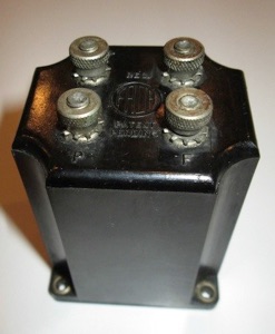

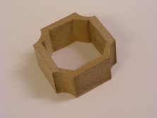
To make this, I glued pieces of 1/4” thick MDF into a box shape, with additional 45° reinforcing in the corners. Then it was run through a router to create the scooped out edges. The picture, below left, shows a piece that was cut off when the enclosure was trimmed to its final size. Finally, the top piece was then glued on and the edge routered to match the contour of the sides. The picture, below right, shows the completed enclosure and the transformer to be mounted inside.

Of all the components, the intermediate frequency transformer was probably the simplest to construct. It is modelled after a Remler model 600 series IF transformer. An authentic Remler is shown below left, and my reproduction is shown below right.
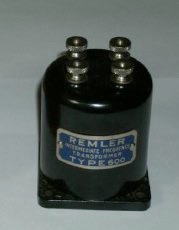
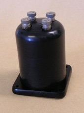
The housing is constructed from a 1.5” ABS pipe cap and a 1.5” ABS pipe coupler. The baseplate is 1/4” MDF painted black. My reproduction is slightly taller than the original because I was concerned about clearance between the top of the coil and the screw terminals.

Holes are drilled in the baseplate to allow access to the trimmer capacitors on the underside of the ceramic insulator.
Of all the fake parts, probably the biggest travesty is the audio output transformer. The following picture shows why.
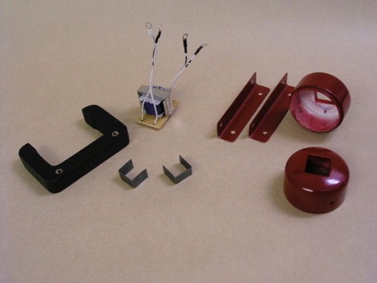
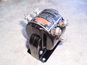 While the other parts are limited to a vintage style housing,
the reproduction audio output transformer includes blatantly
non-functional parts which were quite functional in the original.
Most notable is the fake iron core, which is MDF, painted black, in
my version. The original inspiration was a Rauland transformer as
shown in the picture to the right. I certainly could have hidden the
actual transformer in some other vintage style enclosure, but I find
the style of the Rauland transformer unique and irresistible.
 And so,
I went on a counterfeiting spree. Aside from its actual model number,
the Rauland was branded the “All American.” I decided to paint my
version red, and call it the “All Canadian.”
It is interesting to
note that the functional part, the actual transformer—coil and
core—is small enough to fit completely inside the fake coil
housing. This is largely due to the fact that the total plate current
of the output stage is very low.
The tube sockets were not based on any particular design. However sockets of the early 1920’s era were most often designed for breadboard style construction, and accordingly, had the connections brought out to screw terminals on the top. I came up with a style that appears to be of roughly that vintage. They were straightforward to make, but I found that it was important to do things in the proper sequence.

Inside holes were bored with Forstner bits, and the outside was turned on a small lathe. The following picture shows the parts in different stages of construction.
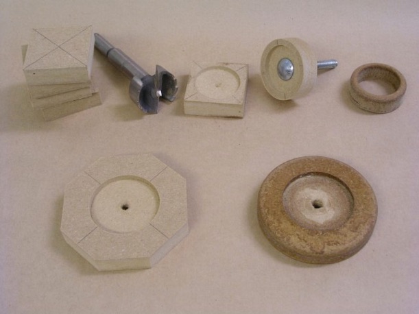
Across the top from left to right are the parts for the centre trim ring beginning with the square blank, the Forstner bit used to bore out the centre hole, a blank with the centre hole partially bored, the piece after being turned on the lathe, and finally the finished trim ring after the centre has been completely bored out. It was necessary to proceed in this order due to the limitations of my lathe chuck. It was necessary to partially bore all centre holes before putting the pieces on the lathe, so that there would be some means to line things up later for the final boring. It was necessary to use a carriage bolt as an arbor to hold the pieces on the lathe. So, the centre holes could not be completely bored prior to the lathe work. Across the bottom from left to right are the pieces for the socket baseplate, starting with the blank on the left and then the piece after the lathe work on the right. The darker colour of the finished pieces is due to a wood sealer that I used to harden the material and improve the finish of pieces during the final sanding.
The following picture shows, the partially finished baseplates with screw terminals installed and the wafer style octal sockets being installed.
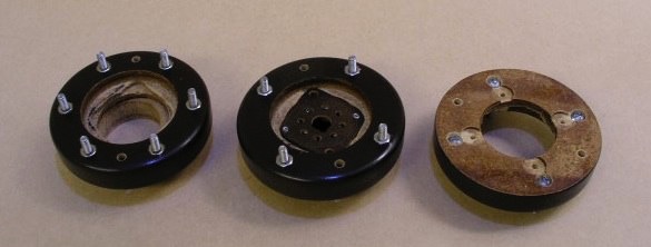
To keep things looking as clean as possible, I only brought out the four or six required connections to screw terminals rather than all eight. The filament voltage equalizing diodes were installed in each base under the wafer socket.
In the following picture, you can see the brass bus bars that I used for B+ and ground connections, and the housings for the RF fine tuning variable capacitor, and the potentiometers for the regen control and volume control.

The bus bars made for a convenient and neat way to distribute power to the various circuit components. However, having two uninsulated bus bars with a potential difference of about 70 volts separated by a little less than 1/2 inch is probably not considered good design practice. So, I insulated them with a clear conformal spray coating of the type typically used on printed circuit boards.
The housings for the RF fine tuning, regen and audio controls are 2” diameter ABS pipe caps. There is nothing especially noteworthy about their construction, except to say that different brands of pipe caps come in slightly different shapes. On these ones, the end is completely flat, while the ones used for other parts (such as the IF transformer) were rounded. So I could choose whichever type that best suited the part. These ones, with the flat end, were ideal for these controls, and made it easy to add the dial scales. The dial scales were simply printed on a laser printer (black toner on yellow card stock) and then glued onto the cap.
—
In summary, even after the electronic design portion of the project was complete, the assembly of the final receiver took several months of my spare time, but I am very pleased with the results, and hope that this may give other hobbyists some useful ideas for their projects.