
Some time ago, while flipping through a copy of the RCA receiving tube manual, I discovered, and was fascinated by, beam deflection tubes which were used as balanced modulators and demodulators primarily in colour TVs. I filed the information away in the back of my mind for a year or two, and then after finding a few other references to the use of these tubes in radio circuits, it occurred to me that one might make an interesting direct conversion receiver. By applying the RF signal to the control grid, and applying a local oscillator signal to the deflection plates at the same frequency as the carrier, the original audio signal will appear at the plates. The primary question was whether this could all be done with a single tube. That is, would there be enough gain between the deflectors and plate for the tube to oscillate by itself? I cobbled together a simple circuit, and determined that it would indeed oscillate by itself. Armed with that information, I proceeded to build the rest of the receiver.
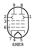
The 6ME8 and 6JH8 are typical beam deflection tubes. While their internal structures differ slightly, and require different deflector bias voltages, the 6ME8 and 6JH8 are functionally equivalent. A signal applied to the control grid (pin 6) will be amplified and appear as an in-phase (common mode) signal at the two plates. On the other hand, any signal applied between the deflector plates (pins 1 & 2) will be amplified and appear as an out of phase (differential mode) signal at the two plates. This allows the different signals to be separated and redirected as necessary. This unique characteristic allows reflexing the audio back through the tube without it breaking into oscillation.
Here is the radio schematic:
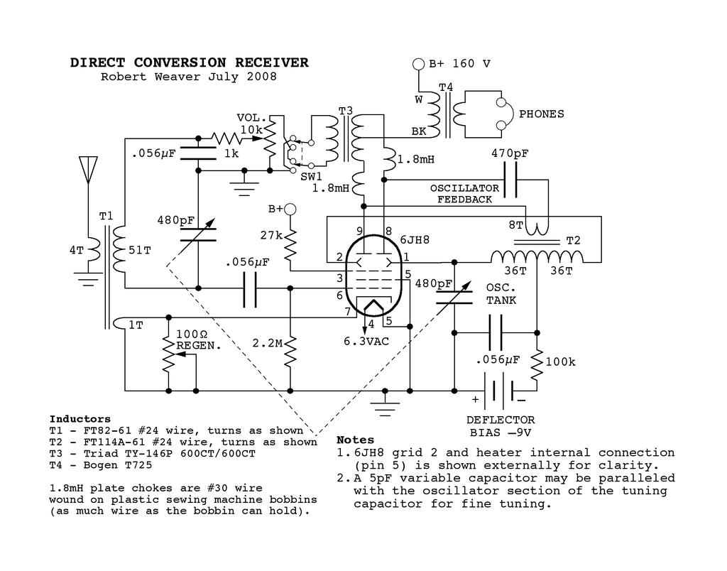
To work as a direct conversion receiver, the RF signal passes through a
tuned RF stage consisting of T1 and one section of the tuning
capacitor, and is applied to grid 1. A signal from the local
oscillator running at the same RF frequency is applied to the
deflectors. The result of this mixing operation is an out of phase
audio signal at the plates. The out of phase audio is detected in T3
and from the secondary is routed back to grid 1. This audio signal is
amplified and appears at the plates as an in-phase signal which
passes through the primary of T3, and being in-phase, it induces no
additional signal in the secondary of T#. The in-phase signal passes
on to T4 where it is impedance matched to the headphones.
Feedback
for the local oscillator is taken as a differential signal between
both plates through a DC & Audio blocking capacitor to the
primary winding of the oscillator coil T2. Half of the secondary
winding forms a parallel tank circuit with one gang of the tuning
capacitor, and feeds back to one deflector. The other half of the
secondary winding provides an equal but out of phase signal for the
other deflector. For best operation the deflectors need a slight
negative bias. With a B+ of about 160 volts, the optimum deflector
bias is about -9 volts, and is provided by a standard 9V battery
permanently wired into the circuit. As there is no current drawn, the
battery will last for its shelf life.
Because the
oscillator circuit operates on differential signals, it seems to be
extremely immune to influence from the incoming RF signal which is
common mode. The result is that the oscillator hardly pulls at all,
even when tuned near a very powerful local station. This in fact, is
almost a detriment, because the tuning has to be precisely on
frequency before the oscillator locks in. To help, the tuning
capacitor has a 6:1 reduction drive, and an additional 5 pF variable
capacitor in parallel with the oscillator section of the tuning
capacitor, is mounted on the front panel for fine tuning. On the
other hand, the stability of the oscillator, allows accurate
calibration of the dial and provides immunity from adjacent stations.
For RF regeneration, feedback for the tickler winding of
T1 is taken from the cathode circuit. By taking the signal from the
cathode, only common mode RF should be present, and none of the
oscillator signal (which should be entirely differential).
All
of this sounds good in theory, but how does it work in practice? I
have to admit, I wasn't expecting this to be a very well behaved
circuit. I had expected that a certain amount of unbalance in the
differential circuits would lead to some spurious common mode audio
cropping up where it wasn't wanted and would lead to oscillation.
However, I also figured that this could be cancelled out by proper
phasing of the secondary of T3 so that it would be fed back
negatively and disappear. It turned out that the circuit was
surprisingly well behaved, and worked pretty much according to plan.
Maybe better. There was a difference in operation depending on the
phasing of the T3 secondary, but it was hard to tell which way was
actually better. By the time I had desoldered the transformer leads,
flipped them and resoldered, then powered up the receiver, listening
conditions would have changed enough that a proper comparison could
not be done.
Finally, I wired up a DPDT switch to reverse
the polarity on the fly. The result was that in one position (which I
will refer to as negative mode) the audio signal level was at a
reasonable level and frequency response was quite flat. With the
switch in the other position (positive mode), the audio level was a
bit greater, and there was some discernible positive audio feedback
which did not necessarily lead to oscillation. It actually provided a
bit of extra audio gain and a bandpass filter effect which sometimes
helped intelligibility of the received signal. With the volume
control turned all the way up, it could go into oscillation. However,
the transition was very smooth as the audio bandpass became very
narrow and began to ring a bit and then finally oscillate. This
behavior was affected by the amount of RF regeneration. With the
regen set at a modest level, the operation was as described. At the
high end of the band, it was possible to turn up the regen quite a
bit to get more RF gain, at the expense of audio stability. As a
result, the audio gain had to be reduced somewhat when the RF regen
was cranked up (especially with the audio phase switch in positive
mode). (It is important to make sure that the regeneration is
strictly working to provide amplification, and not detection.) In the
end, I decided that the DPDT phasing switch should remain in the
circuit permanently in order to pick the best operating mode
according to signal conditions.
Regarding the RF
regeneration, only a single turn was required for the tickler
winding, but in retrospect this probably makes sense considering the
degree of coupling that comes from using a toroid core. In operation,
there was a very abrupt increase in gain as the resistance of the
regen pot was increased just a bit above zero. (This is discussed
further under the Final Notes section.) With further rotation of the
regen control, the gain remained about the same and then decreased
just a bit before finally breaking into oscillation. The optimum
position remained the same for frequencies below about 1400 kHz. And
so I normally left it in this position and didn't touch it again.
Above 1400 kHz, if I was trying to pick up and especially weak
signal, I found that the regen could be turned up quite a bit higher
to get more gain without breaking into oscillation.
In
operation, I found this receiver to be comparable in performance to
my previous homebrew receiver which is a two tube superhet with
reflexed audio. The new set was a bit more complicated to operate
however. It was also somewhat more susceptible to overloading from
powerful local stations. Additionally, my antenna matching unit which
has a significant effect on the amount of received signal, tended to
be more critical with this receiver. As the antenna matcher was
adjusted near to the optimum position, it could cause the receiver to
break into oscillation. I suspect this may be due to the matcher
(being just slightly off frequency) causing uneven attenuation of
upper and lower sidebands which resulted in unbalanced signals
passing through the receiver, and messing up the common/differential
mode signal behavior. This was somewhat annoying, but not an
insurmountable problem. With a bit of practice, I got the hang of
tuning the antenna, and found the receiver quite easy to operate. I
just had to make sure to keep the audio gain turned down until the
everything was tuned in.
Being a direct conversion
receiver, there was never any question about being on frequency.
There was always a clear beat note as each station was tuned in. Even
in situations where no station could be heard, there was almost
always enough of a carrier from some distant station, to get an
audible beat note, and hence there were markers every 10kHz virtually
across the entire band. (I was able to use a second receiver with
digital tuning to check the frequency when necessary. The second
receiver would easily pick up the local oscillater frequency.)
Contest Notes
I used this receiver
in the Summer
2008 Homebrew Contest. Following are the details of antenna,
headphones and other related equipment.
For headphones, Sony MDR-W08 Sport Walkmans were used. Initially,
a pair of homebrew piezo phones were tried, but these required the
use of an extra matching transformer which added enough insertion
loss to negate any benefit of their extra sensitivity. I could have
wired the output transformer as an autotransformer to get a better
match, but I wasn't crazy about having the B+ that close to my ears.
I've come to the conclusion, after using the MDR-W08s in a couple of
DX contests, that they are surprisingly sensitive, not at the level
of sound powered phones, but seemingly better than standard high-Z
magnetic phones. To use the piezo phones in a tube circuit like this
one, I've found that the output transformer needs to have about a 2:1
ratio. A probable future modification will be to find a good 2:1
output transformer, and go back to the piezo phones.
The
antenna used in the contest was a relatively short long wire, about
35 feet strung out in a horizontal L (with each leg about equal
length), running above my deck on the shore of Lake Katepwa. Being
almost right on the water, seems to help bring in those DX signals.
There was also very little local interference, so I was able to make
out quite a few weak signals that would have been otherwise
obliterated.
The antenna matcher is an L network
consisting of a tapped coil wound on a ferrite core, and a 100pF
variable capacitor. An SPST switch allows connection of the variable
capacitor to either the antenna or the receiver side of the coil. The
matcher makes a significant difference in the amount of received
signal, especially when the antenna is as short as this one was.
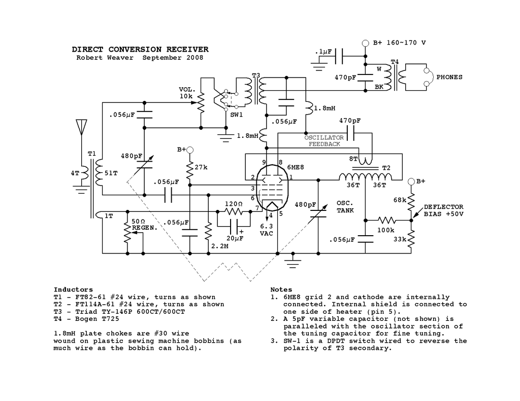
After the contest, I decided to try substituting a 6ME8 for the 6JH8. These are essentially pin compatible. However the 6ME8 requires positive bias on the deflectors, rather than the negative bias required by the 6JH8. I added an adjustable voltage divider from the B+ to find the optimum bias point. With a B+ of about 150V, the best deflector bias was approximately 50V.
The gain seemed to be better with the 6ME8. However, the increased gain highlighted some of the deficiencies of the circuit. I needed to add few bypass capacitors to prevent circuit instability.
Something I had completely overlooked until it was pointed out to me, is that my regeneration method would kill the Q of the RF coil when the regen pot is at zero resistance, creating a shorted winding on the coil. I haven’t done anything about this yet, but did use a different regen arrangement on my next design, and will eventually modify this set as well.
A schematic of the 6ME8 version is shown below:
In addition to changes to the regeneration control (see bottom of the one tube superhet page for proposed regen modification), there are some other future refinements that I plan to make to this circuit, as a result of further experimentation that I did while working on my subsequent project, the 6ME8 one tube double reflexed superhet. These changes relate to the discovery that plate balance appears to be more important than deflector balance. Therefore, a plate balance adjustment should be provided to improve circuit stability. This should allow operating at higher gain without stability problems.