A Simple Nixie Display Driver
November 2019 Update - Note that there is now an Arduino
version of this project.
Most Nixie tube drivers require the obsolete and hard to find 7441 or
74141 TTL decoder driver ICs, or else high voltage driver
transistors. I wanted to produce a Nixie display using easily
obtainable parts (well… except for the Nixies), and at the same
time keep the parts count low. Given the state of the art in power
electronics, it seemed that there should be some modern high voltage
driver ICs available. In fact there are several. However, they are
not always easy to find in the small quantities that experimenters
require.
I settled on an A6818 vacuum
fluorescent display driver from Allegro Microsystems Inc. This chip
was relatively inexpensive, and available in small quantities from
suppliers such as Digi-Key.
Unfortunately, a few months after I built this circuit, the A6818
became obsolete, and inventories of the part disappeared almost
instantly, making this design obsolete as well. Fortunately, a reader
of this page advised me that there is a replacement. It is the Maxim
MAX6922 which has identical specs and identical pinout, and is
reasonably priced like the original A6818. I’ve now tested the
MAX6922, and it is identical in operation, so either one can be used
with no circuit changes. I’ve now revised the writeup, referring to
the driver IC as a MAX6922, but if you manage to locate some of the
older A6818s, they are interchangeable.
The
MAX6922 is a serial in, parallel out, 32 bit source driver, capable
of handling 60 volts, which is sufficient to drive Nixies. Nixies
actually require a sink driver, not a source driver, but the MAX6922
outputs can sink enough current to drive smaller Nixies such as the
Russian IN-16s that I used in my project. With 32 bits, one chip can drive a 3½ digit display.
 The chip comes in a 44 pin PLCC package, which fortunately can be socket
mounted in a through-hole PCB socket. As this picture shows, the
entire driver consists of only two ICs and a few passive parts. The
larger chip is the MAX6922, and the smaller one is a PIC 12F629 8-pin
microcontroller. Because the driver IC is serial input, it requires
only three control/data lines from the controller. That leaves two
I/O pins on the controller available for other functions. As well,
with careful planning, the data line going to the driver IC can serve
multiple functions.
The chip comes in a 44 pin PLCC package, which fortunately can be socket
mounted in a through-hole PCB socket. As this picture shows, the
entire driver consists of only two ICs and a few passive parts. The
larger chip is the MAX6922, and the smaller one is a PIC 12F629 8-pin
microcontroller. Because the driver IC is serial input, it requires
only three control/data lines from the controller. That leaves two
I/O pins on the controller available for other functions. As well,
with careful planning, the data line going to the driver IC can serve
multiple functions.
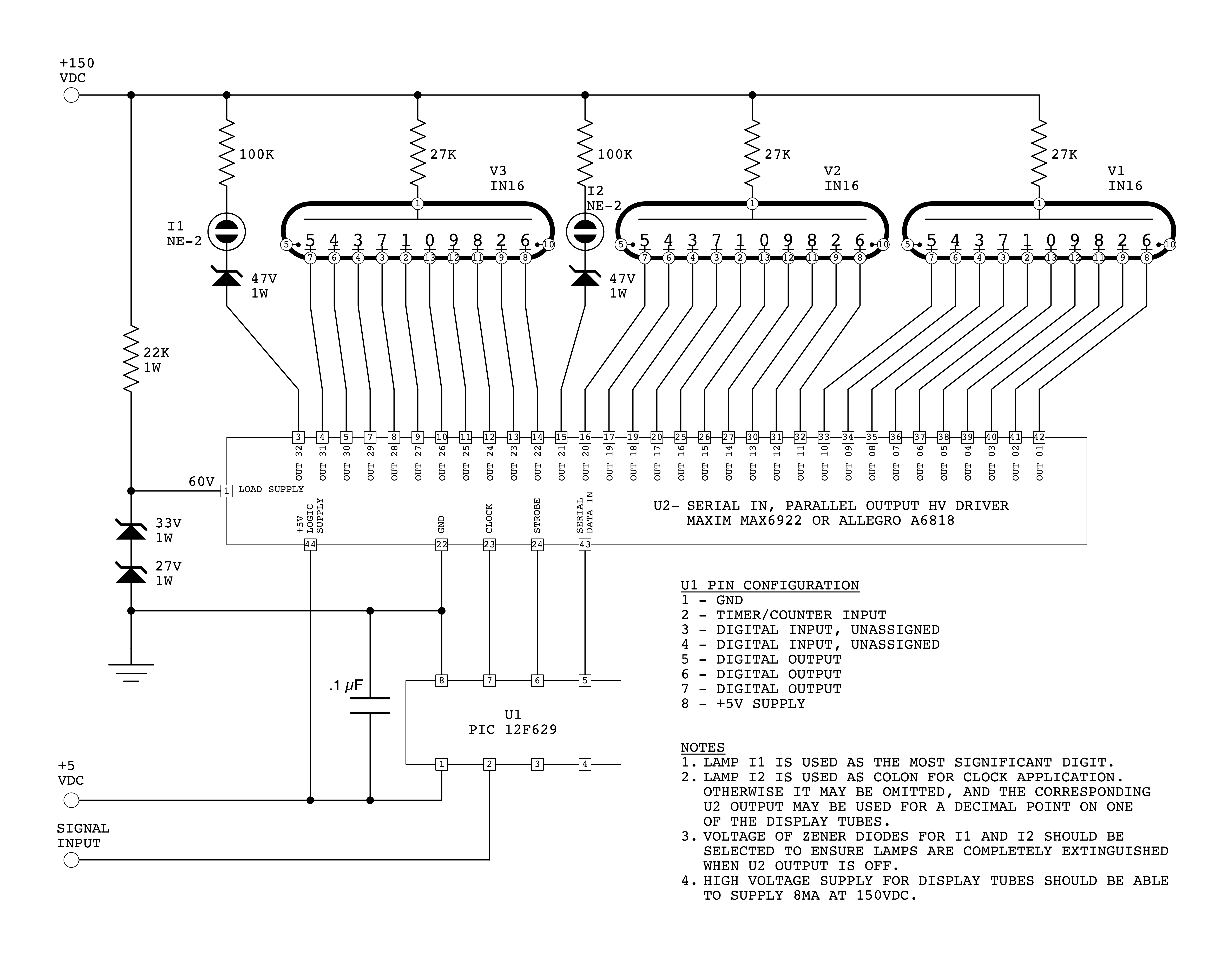
Here is the schematic of the display driver board:

Click for a larger View
One point that deserves some explanation is the requirement to supply 60
volts to pin 1 of the driver IC. This is the voltage supply input
used by the source output drive circuitry, required when driving a
device such as a VFD (vacuum fluorescent display). For a NIXIE
display we only require the sink driver part of the output circuitry.
Therefore, it would appear to be unnecessary to provide a load supply
voltage. However, during testing, it was found that the driver would
not work correctly without having a voltage at pin 1, equal to the
output ‘off’ voltage (approx. 60V). The 22k resistor and series
zener diodes provide this voltage. Note, that an earlier version of
the schematic showed a 60V zener. These are not normally available,
but a 33 volt zener and 27 volt zener, in series, is equivalent. The
current schematic shows this arrangement.
Here is a view of the bottom of the board showing the foil pattern. To
produce the board, I used the toner transfer method (which you can
google; there are several sites which will give a much better
explanation of technique than I will be able to do here).
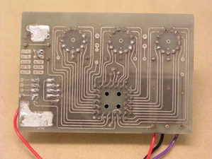 This method
provides excellent results and was the only practical way to create
the required fine traces with minimum fuss and expense. After etching
the board, I used tin plating solution to tin the traces.
Unfortunately, the solution was getting old, and the result didn’t
look very good, and also made it somewhat difficult later to re-tin
the traces when I was soldering on the components. No matter; this
was a prototype, after all.
This method
provides excellent results and was the only practical way to create
the required fine traces with minimum fuss and expense. After etching
the board, I used tin plating solution to tin the traces.
Unfortunately, the solution was getting old, and the result didn’t
look very good, and also made it somewhat difficult later to re-tin
the traces when I was soldering on the components. No matter; this
was a prototype, after all.
I used this first prototype to
make a digital tuning dial for my homebrew radios. However, it could
just as easily be used as a digital clock, thermometer, voltmeter or
other device, depending on how the PIC is programmed, and with a few
additional components. A second MAX6922 could easily be cascaded on
as well, to provide a six digit display.
The digital tuning dial required the addition of a small piggy back
circuit board with the circuit shown here, for some additional
components.
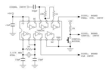 For the tuning indicator, the internal clock was not
accurate enough, and so one pin had to be sacrificed for an input
from an external crystal oscillator on the piggyback board. Another
pin was used for a pushbutton input to allow user configuration. The
data output pin to the display driver was shared with the input
frequency signal, and the remaining spare pin was connected to this
same data pin. This connection is explained below. The piggyback
board contains a signal preamp/conditioner in addition to the crystal
clock. I used a 3.579 MHz television colour burst crystal for the
external clock, as they are inexpensive and I had several on hand.
The actual frequency is unimportant since the unit is calibrated in
the program to suit the clock frequency. The full schematic showing
the controller, display driver and extra components for the complete
frequency display is here.
For the tuning indicator, the internal clock was not
accurate enough, and so one pin had to be sacrificed for an input
from an external crystal oscillator on the piggyback board. Another
pin was used for a pushbutton input to allow user configuration. The
data output pin to the display driver was shared with the input
frequency signal, and the remaining spare pin was connected to this
same data pin. This connection is explained below. The piggyback
board contains a signal preamp/conditioner in addition to the crystal
clock. I used a 3.579 MHz television colour burst crystal for the
external clock, as they are inexpensive and I had several on hand.
The actual frequency is unimportant since the unit is calibrated in
the program to suit the clock frequency. The full schematic showing
the controller, display driver and extra components for the complete
frequency display is here.
To measure the input frequency,
the controller sets up “Count Mode.” In this mode, pin 5 is
configured as a high speed counter, and pin 3 is configured as an
input to prevent it from affecting the signals on pin 5. The counter
is enabled for 10 ms, and the cycles of the input signal are counted.
At the end of this period, pin 3 is reconfigured as an output, and
its low impedance forces the counter input low, disabling the
counter. Only the high order 8 bits of the counter can be directly
read by the program. To read the low order 8 bits, a technique
described in Microchip’s Application Note AN592 is used. Pin 3 is
toggled until the prescaler overflows into the high byte. This is
detected in the program, and the number of times pin 3 was toggled is
equal to the original value of the prescaler. Once both the high and
low byte of the counter are recovered, the IF offset is subtracted
from the count to get the actual receiver frequency. The resulting
number is converted from binary to BCD which in turn is used as an
entry in to a lookup table to determine the correct lines to power on
the Nixie tubes. Pin 5 is now configured as an output for serial data
to the display driver (with pin 3 configured as an input again), and
the line select data is shifted out to the display driver.
The pushbutton connected to pin
4 is used to select which IF offset to use. Most of the common IF
values are stored in a table, and pressing the configuration button
cycles through these to select the desired one.
Final Assembly
I wanted to construct a case
with a retro style to suit the Nixies. For my other radio projects,
I've used MDF (medium density fibreboard) with a dark walnut stain
which somewhat resembles a Bakelite finish.
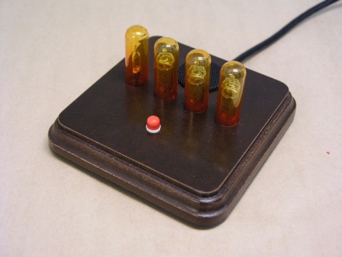
I used the same technique here, with a 5 inch square piece of MDF with
the edges routered, and the bottom hollowed out to accommodate the
circuit board. The Nixie tubes are protected with glass test tubes
which were cut down and tinted amber. The red pushbutton in front is
used to select the IF offset. A small vent hole over the driver IC is
covered by a small circular piece of perforated metal taken from an
old computer speaker.
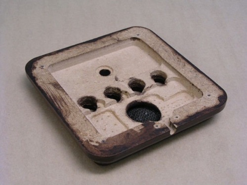
The above photo shows the underside of the housing after it had been
hollowed out using a router. This was done using an extremely simple
box shaped jig built on a piece of scrap plywood. The jig simply
forces the router to stay within a rectangular area within the
workpiece. Some final adjustments were done using Forstner bits in a
small drill press, and a bit of hand chiseling.
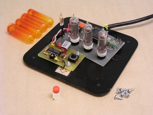
In this photo, the components are shown laid out on the baseplate which
is black painted 1/8” hardboard. Note that the power supply is
external. Although there is room next to the preamp/clock board for a
small switchmode power supply, this would have generated far too much
radio frequency interference to be useable with a radio. Instead, an
analog power supply with a normal transformer was constructed and
mounted in-line in the power cord, much like a laptop computer power
supply.
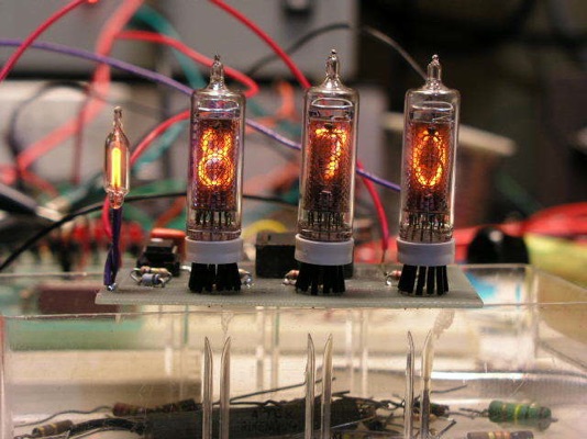
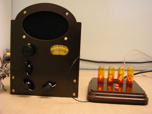
Finally this last photo, below,
shows the unit in operation with my one-tube superhet receiver.
Miscellaneous Bits:
The source code listing for this project is here.
Please heed the warnings in the comments.
I had intended to post circuit board patterns. However, when the
A6818 driver IC went out of production in 2010, a board pattern based
on the A6818 seemed pointless. Now that a drop-in replacement has
been found in the MAX6922, I plan to dig up the PCB files and post
them. I’ve also been looking at upgrades to the original circuit to
handle a full 5 or 6 digits, and hope to have printed circuit layouts
for those available once they are complete.
Back to:
Projects
Home
This page last updated: April 4, 2023
Copyright 2009, 2023, Robert Weaver