1-Tube AM Broadcast Transmitter

2023-02-04 Note: I advise anyone contemplating building this transmitter, that this was my very first
transmitter design, and while it works well, I've since come up with simpler transmitter
circuits that perform just as well. For example The Improved One Tube Transmitter.
However, if you happen to have a 6M11 tube and the other parts on hand, then by all means give this one a try.
This little transmitter came about as a result of my interest in
vintage radio receivers, and the lack of anything worth listening to
on the AM broadcast band (540 - 1700 kHz). With a transmitter, I
could broadcast my own choice of music, and listen to it on my old
radios.
There are a lot of transmitter
projects to be found in Internet-land, including lots of one-tube
circuits. Unfortunately, most of the one-tube circuits use pentagrid
converters which are very nonlinear by design, and tend to produce
very bad sounding signals. I had a few 6M11 compactron tubes that I’d
collected for another project which was never completed. So, I
decided to design my own circuit using one of these tubes. A 6M11 has
two triode sections, and a pentode section. I decided to use one
triode for the oscillator, one triode for the audio preamp/modulator,
and the pentode section for the power amplifier. Screen grid
modulation is used.
Here is the schematic:
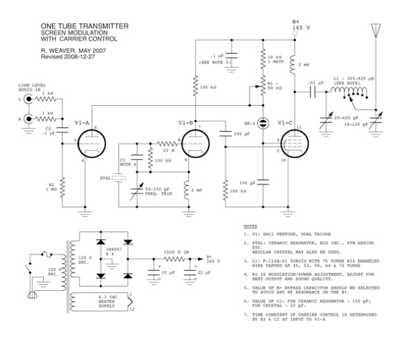
Click for a larger View
How it works
The oscillator section, V1-b, is a standard Colpitts oscillator
using a ceramic resonator (or a crystal). Feedback is from the
cathode circuit. The output of the oscillator section is coupled to
the control grid (G1) of the pentode section. Using a separate
oscillator section, provides excellent isolation from factors which
might otherwise cause frequency drift or frequency modulation. In
testing, I was not able to detect any FM distortion in the
transmitted signal.
Audio preamp section, V1-a amplifies the audio input, and the
resulting signal is DC coupled to the screen grid of pentode section
V1-c through the NE-2 neon lamp. The neon lamp drops the DC level at
the screen by about 50 volts without attenuating any of the audio.
This voltage difference provides a good quiescent operating point for
the pentode while providing a higher voltage at the triode plate. The
variable resistance R1, in the triode plate adjusts the triode plate
and pentode screen supply together for the best operating point. Now,
the obvious question: Why use a DC coupled circuit? Why not use AC
coupling and bias the stages separately to get the best operating
point for each stage? The first reason was simply to minimize any
signal attenuation resulting from all of the extra bias components.
The second reason is that I like neon lamps. The third reason turned
out to be the accidental discovery that this type of DC coupling
allows for carrier control. Carrier control is the principle of
adjusting the average carrier level in a transmitter as the average
modulation varies. At low levels of modulation, the average carrier
value is kept to low values, and at high modulation levels, the
average carrier level is increased. This reduces the average power
consumption of the transmitter, but allows high peak power output
when required. It also has the advantage of working as an audio
expander, and reduces problems of under-modulation and
over-modulation. Once adjusted properly, it’s very forgiving of
changes in audio source levels.
The carrier control works as follows. The preamp grid and input
coupling capacitor act as a clamp circuit. The V1-a grid is biased
very close to 0 volts when no audio is present. With an audio input
signal present, positive excursions of the input signal cause a very
small grid current to flow, which charges the input blocking
capacitor creating a more negative bias on the grid. Hence, the grid
bias voltage follows the peak of the input signal, and positive peaks
of the input signal are clamped to ground level. Therefore, as the
audio input level increases, the grid bias goes more negative, and
the average plate current decreases. When the plate current
decreases, the plate voltage goes up, which in turn increases the
voltage to the screen of V1-c, increasing the average carrier level.
The 1 Megohm grid leak resistor in the grid circuit of V1-a provides
a discharge path for the grid current and the charge on the
capacitor. The value of this resistor and the value of input coupling
capacitor determine the time constant of the carrier control. The
values shown in the schematic seem to be optimum for correct carrier
attack/decay time, and give the best sound quality.
Output from the plate of V1-c is coupled to the antenna through a
pi matching network. I used a tapped coil, because I wasn’t
familiar enough with antenna matching (especially with a random
length antenna) to zero in on the best value. Also, the optimum
inductance will vary depending on the operating frequency of the
transmitter. The coil shown in the schematic covers the AM broadcast
band fairly well, when coupled to reasonably short antennas (~10 feet
long).
Sound quality from this transmitter is excellent. It is easily
capable of delivering an acceptable signal even to hifi AM receivers.
I tested this with a Sony ST-JX450A AM stereo, FM stereo tuner, which
is capable of wideband AM reception. In wideband mode, the audio
quality was better than what I could receive from commercial AM
stations.
This transmitter does have a couple of shortcomings though. The
first is that it requires a bit more than line level audio to drive
it to full modulation. This could be overcome by using an audio input
transformer to increase the drive level, or add an additional preamp
stage. I use an inexpensive Radio Shack mixing console which puts out
enough signal to drive the transmitter quite well.
The second shortcoming is that even with three stages, this
transmitter doesn’t put out as strong a signal as you could get
from a one tube circuit using a dual control pentode with suppressor
modulation. However, it has enough output when properly matched to a
10 foot antenna to be heard over a distance of 100 feet, which is
enough to get to any radio in my house.
Here is a view of the underside of the chassis:

Wiring is point to point, using the tube socket for mounting many of
the components. This results in very short lead lengths which is good
for radio frequencies, even though it doesn’t necessarily look very
neat. The toroidal chokes shown in this picture were later found to
be extremely lossy, and were replaced with better ones. Never use
mystery ferrite! Immediately in front of the tube socket is a part of
an IC socket which is used to hold the ceramic resonator, but the
resonator is missing in this photo.
Here is a view showing the transmitter
 with the antenna matching network, which was built as a separate unit
The audio source is from the MP3 player in the foreground. In the
background is an inexpensive passive signal strength meter, which I
used for adjusting the matching network for maximum output. Antenna
matching is a critical part of setting up any transmitter, especially
something as low powered as one of these. When correctly adjusted,
the amount of power to the antenna goes up dramatically, and is
clearly visible on the signal strength meter. The red wire connected
to the matching unit is the base end of a 10 foot wire antenna. The
signal strength meter is about a foot away, and is sensing the signal
with a small 4 inch built-in antenna (beyond the right side of the
photo).
with the antenna matching network, which was built as a separate unit
The audio source is from the MP3 player in the foreground. In the
background is an inexpensive passive signal strength meter, which I
used for adjusting the matching network for maximum output. Antenna
matching is a critical part of setting up any transmitter, especially
something as low powered as one of these. When correctly adjusted,
the amount of power to the antenna goes up dramatically, and is
clearly visible on the signal strength meter. The red wire connected
to the matching unit is the base end of a 10 foot wire antenna. The
signal strength meter is about a foot away, and is sensing the signal
with a small 4 inch built-in antenna (beyond the right side of the
photo).
Here is a trapezoidal scope trace showing the modulation envelope,
when at approximately 100% modulation.
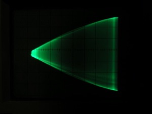 Note that the
curvature in the envelope indicates the presence of some distortion.
This was not audible however, and I didn’t consider it significant
compared to the severe type of distortion which would occur from
over-modulation. When the audio level is changing, the carrier
control effect is very noticeable, as the zero percent modulation
point on the left hand side remains stationary, and the wide full
modulation part on the right, expands further to the right in time
with the audio.
Note that the
curvature in the envelope indicates the presence of some distortion.
This was not audible however, and I didn’t consider it significant
compared to the severe type of distortion which would occur from
over-modulation. When the audio level is changing, the carrier
control effect is very noticeable, as the zero percent modulation
point on the left hand side remains stationary, and the wide full
modulation part on the right, expands further to the right in time
with the audio.
Antenna Matching Update - 2015-09-07
Please refer to this page for updated information about:
Matching a
Part 15 transmitter to a short antenna
It discusses the antenna pi matching network used in the above
schematic, as well as a simpler and more efficient antenna matching
network.
Back to:
Projects
Home
This page last updated: February 4, 2023
Copyright 2009, 2023, Robert Weaver
