455 kHz Signal Generator
A stable 455 kHz signal generator is a useful piece of equipment for
the radio hobbyist. It can be used for aligning the IF (intermediate
frequency) section of a receiver, and it can be used as a BFO (beat
frequency oscillator) for receiving CW and SSB signals.
The following circuit uses a 455 kHz ceramic resonator
 which gives good frequency
stability, but still allows for fine frequency adjustment. I've built
both a very simple low parts count version as shown in the schematic
to the right, and a deluxe version. Both are inexpensive, and the
circuits can be customized as necessary to add or delete features.
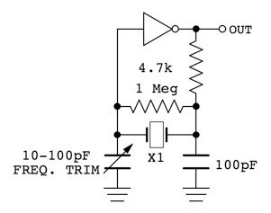
The barebones version is just a 455 kHz square wave oscillator and
nothing more. You can even leave out the trimmer, replacing it with
a fixed 100 pF capacitor, and have more than enough accuracy for
aligning receivers.
which gives good frequency
stability, but still allows for fine frequency adjustment. I've built
both a very simple low parts count version as shown in the schematic
to the right, and a deluxe version. Both are inexpensive, and the
circuits can be customized as necessary to add or delete features.
The barebones version is just a 455 kHz square wave oscillator and
nothing more. You can even leave out the trimmer, replacing it with
a fixed 100 pF capacitor, and have more than enough accuracy for
aligning receivers.
Note that the power connections to the logic chips are not shown. For all of
the integrated circuits shown in the schematics, the positive supply
connection goes to pin 14, and the negative (ground) supply
connection goes to pin 7. It is the same for both the Hex Inverters
and the Quad Nand gates.
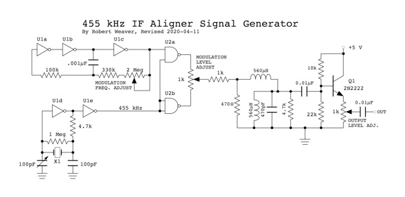
The deluxe
version produces a very clean sine wave with adjustable amplitude
modulation, and has a buffered output. The original deluxe version
used a ceramic filter in addition to the ceramic resonator. However, the
ceramic filter has now become very hard to find. Therefore, I revised
the circuit, replacing the ceramic filter with a simple LC filter.
The original version of the circuit also had a fixed output impedance
of about 300 ohms, but it required an additional transistor connected
as an emitter follower. For radio alignment use, I decided that this
was unnecessary complexity, and I omitted it from the new version.
Here is the schematic of the deluxe version:
Click for a larger View
For reference the original deluxe version schematic is Here
Parts List
U1 - CD4069 or 74C04 CMOS hex inverter
U2 - CD4011 or 74C00 CMOS quad NAND gate
X1 - 455 kHz ceramic resonator, ECS Inc. ZTB455E
Other parts values are as indicated. Transistor type is not critical. Any
general purpose type should work fine. I used a 2N2222. The 560 µH
inductors are commonly available moulded chokes such as JW Miller
Series 78F.
Important Note: If 74HC parts are used, then the maximum supply voltage is 5 volts.
Circuit Notes
Inverters U1a, b & c form a low
frequency oscillator used to modulate the 455 kHz carrier. With the
component values shown here, the frequency can be varied over the
range of about 250 Hz to 5 kHz.
Inverters U1d & e along with
ceramic resonator X1 form a stable (0.5%) 455 kHz oscillator.
NAND gate U2a is the modulator and
provides a 100% square wave modulated signal. NAND gate U2b buffers
the original unmodulated signal, and its propagation delay ensures
that its output is in phase with the output of U2a. So,
the Modulation Level pot blends between the completely
unmodulated signal at the bottom end to a 100% modulated signal at
the top end.
The modulated signal passes through a
bandpass filter consisting of the two 560 µH inductors and the 330pF
capacitor, removing the harmonics and producing a clean sine wave.
Transistor Q1 is an emitter follower
which puts a constant load on the bandpass filter, and buffers the
output.
Power supply voltage is not critical.
If you use standard CMOS IC's, a supply voltage between 5 and 9
volts is recommended.
Back to:
Projects
Home
This page last updated: February 3, 2023
Copyright 2010, 2023, Robert Weaver
