

I'm always on the lookout for transformers which may be suitable for use in electronics projects, and especially vacuum tube circuits. One source that I discovered a few years ago, is the "razor outlet" isolation transformer. In North America, and I believe Europe as well, electrical codes prohibit the use of a normal electrical outlet in bathrooms. However, outlets which are isolated from ground are permitted for powering electric shavers. Shown below are front and rear views of a typical razor outlet which was once common here in Canada (and elsewhere, I assume):
With the advent of ground fault circuit interrupters, these are now mostly obsolete, but they can still be found at electrical salvage shops. At one shop near my home, there is a never ending supply of them, and they are very inexpensive.
These are isolation transformers with a 20 volt-amp rating and approximately 1:1 turns ratio. The secondary actually has slightly more turns than the primary to compensate for voltage droop at full load. When the secondary voltage is rectified and filtered, it can produce a DC voltage of 150 to 175 volts which is suitable for many small, one or two tube, vacuum tube projects. If these transformers had a heater winding as well, they would be ideal. As it turns out, it's quite easy to add a heater winding. In every case that I've encountered, there has always been enough room on the bobbin to add the heater winding.
However, the very first requirement is to make sure that the transformer is in good working condition. Initial tests should be done to ensure that there are no internal shorts. The first time it's powered up, it may be wise to use a Dim Bulb Tester. However, I simply applied the full mains voltage, and kept my hand on the switch, ready to shut it off quickly if it hummed loudly. Passing this initial test simply meant that there were no really bad shorts. However, this would not detect one or two shorted turns. So the next test was to keep the primary powered up for a long period and checking the temperature every few minutes. Under no-load conditions, these transformers will get a bit warm but should never get hot. I suggest leaving the transformer powered up for at least half an hour. If it becomes more than just warm to touch, then it is defective and should not be used. If if passes these initial tests, then we can proceed to do a few simple measurements and add the heater winding.
In the following discussion, I will describe, step by step, a method for adding the heater winding to an existing transformer. Although I will be using the razor outlet transformer similar to the one pictured above, the method should be applicable to any small power transformer. There are quite a few photos, and a lot of description, which may imply that this is a complicated procedure. On the contrary, it’s quite simple to do, and as long as a person has a few basic hand tools and uses reasonable care, there should be no problems.
The transformer being used for this example has the following nameplate data:
Primary voltage: 115
Secondary voltage: 115
Volt-Amps: 20
It's necessary to find out how many turns are required on the heater secondary. We can disassemble the transformer and make trial windings, but it turns out that disassembly is unnecessary. Instead, the procedure is to leave the transformer intact, and add a test winding of approximately 10 turns of very small gauge wire, which is thin enough that it can be threaded though the core aperture and wound around the bobbin with little effort.
To avoid wasting wire, we take some physical measurements of the transformer. From the following image, it can be seen that the outside of the winding is 3.8 by 4.4 cm.
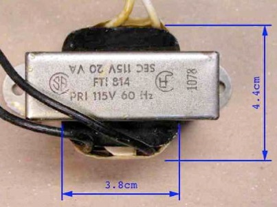
Therefore the length of one turn is approximately 2 x (3.8 + 4.4) = 16.4 cm.
So, ten turns will be 164 cm. I added an additional 20 cm for leads, for a total of 184 cm. For the test winding I will use #32 AWG (0.2 mm) enamelled wire. However, the actual size is unimportant. You can use whatever size you have available. But of course, smaller wire will fit through the core aperture more easily than larger wire.
In order to prevent damage to the thin enamel insulation from the sharp edges of the laminations, I covered the exposed edges with masking tape. This is easily done by cutting a long strip of masking tape, and folding one end over, sticky side to sticky side as shown below:

This makes it easy to push the tape through the thin opening without it sticking to anything.

After it is passed through the opening, it can be pressed in place and then trimmed. The transformer, ready for the test winding is shown below. And beside it is the wire for the winding, a total length of approximately 184 cm as previously mentioned.

Following is the transformer with the completed test winding:

Because the core measurements had been quite generous, there was more than enough wire to wind the 10 turns. I used all of the available wire leaving just enough for leads, and ended up with 13 turns. More turns means better accuracy.
We are now ready to take some measurements.
For convenience, I decided to use two meters so that I could take two readings at the same time. So I compared their calibrations by reading the mains voltage:

As you can see, they are quite close, but there is a small difference. The meter on the left was arbitrarily deemed to be the standard, and hence the readings on the smaller meter are then scaled up by a factor of 120.3/119.6 = 1.00585.
With the transformer powered up, the following photo shows the voltages on the test winding (left), and the original secondary winding (right):

From the test:
Primary voltage VP = 120.3 (previous photo)
Secondary voltage VS = 130.4 x 1.00585 = 131.2
Test winding voltage VT = 2.027
From these measurements, the volts per turn VN can be immediately calculated:
VN = 2.027 volts / 13 turns = 0.15592 Volts/turn
We can therefore infer that the primary winding is 120.3/0.15592 = 771.55 turns.
To add a heater winding, the simple solution is to divide the desired heater volts by the volts/turn to get the required number of turns for the winding. For a 6.3 volt winding:
6.3/0.15592 = 40.4 turns
While this would give a result which is close to the required number, it does not account for the effect of loading on the transformer. Note that for an input voltage of 120.3 volts, with no load, the secondary winding produces 131.2 volts. Obviously, the turns ratio is not 1:1 even though the transformer's rated output voltage is the same as its rated input voltage. The secondary has a few more turns than the primary to compensate for loading effects. The actual turns ratio from the primary to the HV secondary is:
131.2/120.3 = 1.091
We will refer to this ratio as the Voltage Droop Factor kD.
If we multiply the 40.4 turns by the voltage droop factor, 40.4 × 1.091 we get 44 turns. That is the number that will be used for the heater winding.
However, it should be noted that this is still a simplified approach, and the actual output voltage of the heater winding will vary depending on the total tube heater load, as well as the high voltage secondary load. I have developed a more accurate formula for determining the required number of windings for the heater, based on actual heater and HV current draw, and I will post this information on a separate page, in the near future. But for now, we will use 44 turns, and later I will show a simple method to compensate for heater load after the transformer has been wound and tested.
Following are photos showing the disassembly of the transformer. First, bend up the tabs holding the saddle bracket to the transformer. You can use wire cutters...

... or a screwdriver:

It's not necessary to bend the tabs up a full 90°; just bend them up enough that they no longer contact the core.
Then, using a screwdriver, pry the saddle bracket outwards so that the tabs completely clear the core:
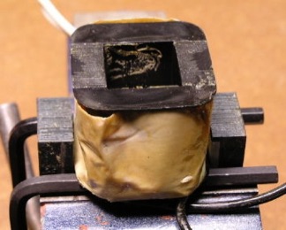
Now, the core is ready to be lifted out of the saddle bracket.

Core partly disassembled:

As you can see, the laminations are not interleaved, which makes it easy to disassemble. A sharp rap with a small hammer will break away the brittle varnish that holds the I-laminations in place.
Now, set the core loosely in a vise with the bobbin supported, and carefully drive out the "E" laminations. Again, a few sharp raps with a hammer breaks the varnish and does the trick.

Notice that I've placed a pair of Allen keys between the bobbin and the vise, so that the leads are kept clear, and not damaged.
After a couple of taps with the hammer, the "E" laminations are nearly out:
And, here is the core completely disassembled.

At this point it is necessary to remove most of the tape covering the windings. In most cases it has been applied rather sloppily, and mingled with great gobs of petrified varnish. Without removing it there won't be enough room to add the heater winding.

It's important to be extremely cautious at this point. As you can see, on the left side of the photo, part of the windings are already exposed. If you use any kind of a metal tool to cut or pick at the tape, you run the risk of damaging the enamel insulation on the wire, or even breaking the wire itself. I recommend using a wood or plastic tool at this stage. Bamboo skewers, which are sold in some grocery stores, are useful for this. They have a sharp point on one end, but they are not hard enough to damage wire or insulation. The important thing is not to hurry. Take your time.
After a bit of patient work, most of the tape has been removed exposing the windings:

Notice that in these isolation transformers, the primary and secondary windings are side by side. The moulded bobbin has a central flange between the windings which is an added level of safety, keeping the windings completely isolated from each other.
Make special note of the white leads which connect to the secondary winding. The upper one in the photo is connected to the start of the winding. It is brought up along the central flange and was wrapped with insulating tape when it was wound. Without this tape, the only thing separating this lead from the top of the winding–which is at a 120V difference of potential–is the thin enamel insulation. Therefore, it's important to make sure that this lead remains well insulated from the rest of the winding during the upcoming work.
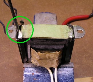
An additional useful safety feature, which cannot be seen in the above photo, is a self-resetting bimetallic circuit breaker on the opposite side of the winding from where the black primary leads are connected. I didn't unwrap enough tape from the primary leads to expose it on this bobbin, but the following photo shows another core which I worked on some time ago, and shows the circuit breaker embedded in the primary winding:

Even though the secondary winding is a bit taller than the primary, I recommend winding the heater winding over top of the secondary, rather than over the primary. This keeps all of the secondary windings well isolated from the primary.
For the next steps it's important to mount the bobbin securely and to move the primary and secondary leads out of harm's way. As you can see, the exposed ends of the secondary winding, where the leads are connected, are very fragile, so caution is required. If you wish, you can unsolder the leads in order to avoid mechanical stress on the fine wires. However, I've found that it generally works well enough to tape the leads back out of the way.

Here the bobbin has been mounted on a wood mandrel which in turn is mounted in a vise. I've used rubber bands, and a bit of masking tape to secure the leads out of harm’s way. Now after all the work of removing the tape from the windings, we turn around and tape them up again:

However, this time, we do it very neatly, keeping the tape tight against the windings, so there's room to add the heater winding. The tape provides isolation between the high voltage secondary and the heater winding. Here I've used Kapton tape, because it has very good dielectric properties, is suitable for high temperatures, and is very thin.
The next photo shows the taping complete, and the bobbin rotated 180 degrees, showing the primary leads and some insulating paper which is still attached to the primary leads:

I didn't attempt to remove this paper. I just lifted it out of the way, so that I can proceed with the heater winding.
In the next photo, I've taped the starting end of the heater winding in position. I used ordinary masking tape here. Because this is a low voltage winding, the insulation voltage rating is not a concern.

The actual winding is now ready to commence. Before starting any coil winding adventure, it is always important to have a few pre-cut pieces of tape ready, to hold things in place, in case your work gets interrupted:

Now, simply wind the wire around the bobbin, remembering to count the turns as you go.
It's critical to make sure that the winding does not bulge out beyond the bobbin flanges on the sides where the laminations fit. However, they may stick out on the sides where the leads are located. It's easy to make the first layer quite neat, but the subsequent ones, inevitably will be a bit messy. This doesn't matter though.
Luckily, I had the little pieces of tape ready, because I was on turn number 8, when I was interrupted by someone at my front door. Fortunately, I had the pieces of tape handy, to stick things down. I also wrote down, on a pad of paper, the number of turns which I'd completed, just in case there were more interruptions before I got back to the winding.
Eventually, I completed the winding of 44 turns, and stuck another piece of tape over the end of the wire to hold it in place:

Then I added a couple of layers of Kapton tape. The high voltage leads will be folded over the top of the heater winding, so, the extra insulation value is necessary.

Rather than solder flexible leads to the heater winding wires, I simply slipped some green spaghetti tubing over them. Since I planned to use the transformer immediately, I didn't feel the added work to strip the enamel close to the bobbin and solder on leads would be necessary. The #24 wire is quite sturdy, as long as it isn't flexed too many times.
If you wish to use flexible leads, then it's a good idea to solder the first one on, before starting the winding. Then, wind the wire. To do the second lead, find where the last turn ends, mark it, and unwind a couple of turns so that you have a bit of room to work. Then solder on the lead, and wind the loose wire back onto the bobbin.
Once the heater winding was complete, I folded the high voltage leads back over, and taped them down. Then, I wrapped a few layers of Kapton tape over the primary. Finally, I wrapped the entire bobbin with a couple of layers of black fabric tape. The completed bobbin is shown in the next photo:

At this point I did some continuity checks to make sure there were no broken windings and no shorts from one winding to another. Everything checked out okay. So I was ready to reassemble the transformer.
There is nothing noteworthy about the reassembly. It's just the reverse of the disassembly. However, do try to get the laminations fitting together as tightly as possible. You may also find it useful to apply some electrical varnish to help hold things together more securely, and prevent vibration of loose parts.
The completed transformer is shown in the next photo:

The first test is to measure the resistance between the core and each of the leads, to make sure that no shorts occurred during reassembly. A digital multimeter should show infinite resistance between each lead and the core. Then repeat the resistance measurements between the different windings to ensure that there are no winding to winding shorts.
The next test will be a simple measurement of voltage of the heater winding with no load. The predicted no load voltage is equal to the number of turns on the heater winding multiplied by the volts per turn value VN that was determined from the test winding, and corrected by the change in input voltage. The original test input voltage was 120.3 volts. The input voltage, at the time of this later test, is 119.5 volts. This test is simply a confirmation that I didn't miscount the turns when I wound the heater winding. The no-load heater winding voltage VHo should be
VHo = (119.5/120.3) 44 × VN = (119.5/120.3) 44 × 0.19952 = 6.81 volts
In the following photo, it can be seen that (with 119.5 volts applied to the primary) the open circuit voltage on the heater winding is 6.62 volts. So, it appears that I did indeed miscount the turns as I was winding the transformer. For 43 turns the calculated no-load voltage is 6.66, and for 42 turns it would be 6.51 volts. So, it appears that I put 43 turns on the heater winding rather than the intended 44. (It’s quite easy to lose count.)

It's not the end of the world though. I mentioned earlier that the final voltage can be adjusted for heater load (or winding errors, as the case may be). First, it’s best to test the transformer in the intended application, under normal load. If the heater voltage is too high or too low when under load, then it’s a simple matter to add a boost/buck winding to compensate. Simply thread one or more turns of #22 PVC insulated hookup wire through the core aperture, and connect this in series with the heater winding. At this stage, there will likely be more room to do this over top of the primary winding, but the PVC insulation of the hookup wire is more than adequate for this service.
To increase the voltage, these turns should be connected series aiding, and to reduce the voltage, they should be connected series opposing. Each turn of the boost/buck winding will change the output heater voltage by VN, or about 0.16 volts. So, if the voltage is 0.5 volts too low or too high, add a 3 turn boost/buck winding. It’s unlikely that the voltage will be off by more than a half volt.