Use this calculator to find the inductance of a multi-layer coil.
For single layer coils, you may
also use the following simpler calculators:
Solenoid
Inductance Calculator
Rectangular
Coil Calculator
Refer to the bottom of the page for explanation of input variables and other notes.
Note: This calculator is also suitable for flat spiral (pancake, spiderweb, etc.) coils, by setting the number of turns per layer, NT to 1 and setting the number of layers NL to the number of turns in the spiral.
See bottom of this page for detailed information and instructions.
Revised 2023-01-29
Please scroll to the bottom of the page for a detailed revision history.
Note that as of the 2019-03-03 revision, you now have additional input options for coil length/pitch, winding depth/pitch and coil diameter. Previously, all of these dimensions were measured from centre to centre of the applicable conductors (as shown in the diagram below). This means that the inner diameter would be one wire diameter greater than the coil form diameter. This made it a bit cumbersome for the user. Now, the input options in the popup menus include the actual coil form dimensions and overall dimensions as well as the original centre-centre dimensions. The original centre-centre menu options are now indicated with “C-C” to avoid confusion. The displayed output values for Coil Length and Coil Outside Diameter are now all overall dimensions. An additional diagram will be added at a later date to show the new dimension types.
Please refer to the diagram below for terminology.

All length, diameter and pitch measurements are from centre to centre of the conductors as shown.
* The notation C-C indicates that the dimension is measured from centre to centre of the conductors as shown in the diagram.
Uppercase D parameters refer to overall coil diameters while lowercase d parameters refer to conductor diameters.
Calculation Method:
This calculator uses Maxwell’s formula
for the mutual inductance between two circular filaments, applied to
every combination of wire pairs in the coil, and then summed to
determine the total inductance. For polygonal coils, an equivalent
circular coil is determined according to a method by F. W. Grover,
and the inductance is calculated from the equivalent coil. More
information about these calculations is given in Calculation
Methods Part 1c.
Wire size:
You may enter conductor size either as diameter in
mm or AWG gauge number in the Conductor Size field. Select either
‘AWG’ or ‘mm’ from the popup menu as appropriate. When
entering conductor size as AWG, sizes larger than 0 may be entered
as 00, 000, etc., or 2/0, 3/0, etc. Although AWG sizes larger than
4/0 do not officially exist, the calculator will accept them and
handle them according to the AWG standard ratio between successive
sizes of 1.1229322.Insulation diameter di
is required to be entered only in the case of a close wound coil
(see next item). For enamelled magnet wire, you can leave the Auto
Calculate box checked, and the calculator will automatically
determine the insulation diameter. For other insulation types,
uncheck the Auto Calculate box, and enter the actual insulation
diameter in the Wire diameter including insulation field.
Close Wound Coils:
For close wound coils, set the axial and
radial dimension fields to zero or leave them blank. In Wire
diameter including insulation field, enter the value for the
insulation diameter, or check the Auto Calculate box as explained
above. The calculator will automatically set the correct winding
pitch.
Universal/Honeycomb/Basket-weave Coils:
Inductance is
essentially independent of the order in which the turns are placed
on the coil. As long as it is possible to count the turns per layer
and number of layers accurately, then the calculator will determine
the correct inductance. In the case of these space wound type coils,
it may not be easy to determine the effective number of turns per
layer beforehand, making it difficult to predict the final
dimensions, and hence, the inductance value. However, coil length ℓA
is easily determined beforehand, and if a test winding is made,
total turns, and number of layers can be easily counted. From this
test winding data, the turns per layer can be found by dividing
total number of turns by number of layers. This information can then
be used to design the final coil.
Frequency Correction:
Optionally, enter the intended operating
frequency, and the calculator will calculate a frequency correction
due to skin effect. This correction is very small and can be
neglected in most cases. Note that no correction is done for
proximity effect.
Self-Capacitance Effect:
The effect of self-capacitance causes
coil inductance to read lower than its true value, when measured on
inexpensive inductance meters. Because multi-layer coils tend to
have much higher self-capacitance than single layer coils, the
difference between measured and true inductance can be expected to
be greater. Therefore, one should be cautious when interpreting the
measurements from inductance meters if they appear lower than
expected.
Coil Form Shape:
The coil form may be either circular or
polygonal. For polygonal coils, select Polygonal from the Coil form
popup menu, and then in the Number of Polygon Sides input field,
enter the number of sides. For circular coils, leave the popup menu
set to Circular, and leave the Number of Polygon Sides input field
blank.
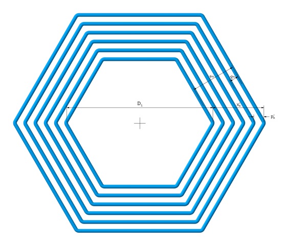
Polygon Measurements (see diagrams below):
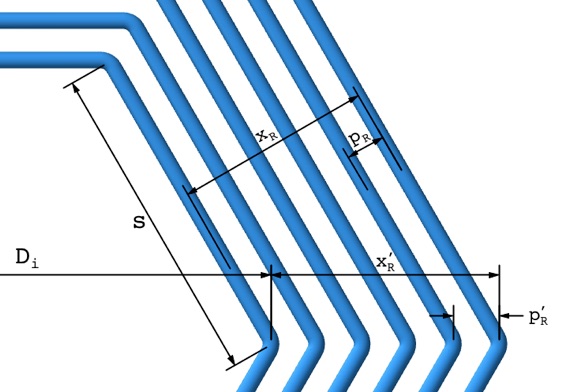
Inner diameter Di
is the same as the diameter of the circumscribed circle of the inner
polygon. It is measured, in the case of a polygon with an even number
of sides, from one inner vertex across to the opposite inner vertex.
For a polygon with an odd number of sides, the measurement is taken
from the centre axis to an inner vertex, and that value is then
doubled. Alternatively, measure the length, s, of a side, and
then the diameter is given by:
Di = s/sin(π/NS) (Angle in radians)
or
Di = s/sin(180/NS) (Angle in degrees)
Note that the true radial pitch pR is less than the radial distance between vertices pR', by a factor of cos(π/NS). Likewise, the radial depth of winding, xR, is smaller than xR', the distance between the innermost and outermost vertex by the same factor. However, since it is generally easier to measure along the vertices, the calculator is designed to accept the pR' and xR' values as measured along the vertices. Therefore: Do not use the pR and xR values for polygonal coils.
Viewed along axis:

Dimension detail:

Back to:
Calculators
Radio Theory
Home
This page last updated: January 28, 2023
Copyright 2010, 2023 Robert Weaver
2023-01-29
This page has been completely rebuilt and uploaded in conjunction with a major update of the site to replace the original web development software.
The calculator portion of this page is no longer embedded in an iframe, which should finally fix some known issues with the bottom part of the calculator being cut off in some browsers.
2019-03-03
The 2017-11-30 revision did not correctly address some of the displayed calculated dimensions. There were also several calculation errors caused by incorrectly calculating length as NT × P (Number of Turns × Pitch) when it should have been (NT – 1) × P. Similarly, coil depth calculations were incorrect due to using NL instead of NL–1, where NL is number of layers. The result of these, in most cases, was simply the incorrect display of the coil length and diameter. However, in certain instances, it could also have resulted in an error in the calculated inductance, depending on the selected input popup menu options. The amount of error would vary from negligible for large NL and NT (greater than 20), to fairly significant for small NL and NT (less than 5). Many thanks to the people who noticed the error and reported it: Richard, Brad, Sam and Walt.
Added additional input options for entering coil length and diameter.
2017-11-30
Minor calculation changes to address errors in the displayed coil dimensions.
2015-08-24
Entire site rebuilt and uploaded using updated web publishing software. This should address the issue of the bottom part of the calculators being cut off on some web browsers, which made some display fields invisible.
2014-01-28
Original version uploaded.