My original One-Tube
Transmitter was built using a 6M11 tube which I just happened to
have on hand. Although it works very well as is, I decided that the
design could be improved and simplified, by using a tube having
characteristics specifically suited for the various functions. The
first change was to eliminate the separate oscillator section. With
frequency being controlled by a crystal or a ceramic resonator, a
modulated oscillator should have more than adequate frequency
stability and freedom from FM distortion. With this decision
made, the possible candidate tubes increased considerably. Dual
section tubes are much more common than triple section tubes.
I also decided that this new
transmitter would use carrier control, as did the previous design.
This is because of an issue which crops up when using simple
transmitters. That is the need for some sort of compressor/limiter
audio pre-processing to prevent over-modulation and under-modulation.
If the audio source is from audio files stored on a computer, then
it's possible to use audio software to perform the compression and
limiting function. But, if the audio source is some other device,
then one is left with the choice of either:
Keeping the audio level low enough that the peaks won't over-modulate the transmitter;
Buying or building an add-on compressor/limiter.
Option a. costs nothing, but tends to be unsatisfactory if the program sources
vary widely in dynamic range, as is usually the case. Option b.
involves additional circuitry which offsets the simplicity of the
original transmitter design.
The carrier control option
avoids the problem by adjusting carrier level automatically as the
program source level changes, maintaining a high modulation level at
all times, and thereby compensating for changing levels. As was
mentioned in the original
transmitter article, the carrier control is implemented by
biasing the input triode grid to ground potential, and using the
resulting grid clamping effect. A bit of research revealed that this
works best with a high transconductance triode. On that basis, I
chose a 6CQ8 dual section triode/tetrode for the transmitter. The
triode transconductance is a suitably high 8000 µMhos. Another
requirement for carrier control is the direct coupling from the
triode plate to the modulator tube screen. Hence, screen modulation
is used rather than plate or suppressor modulation. Tetrodes exhibit
better linearity than pentodes when screen modulated. Therefore, the
second section being a tetrode made the 6CQ8 an ideal choice.
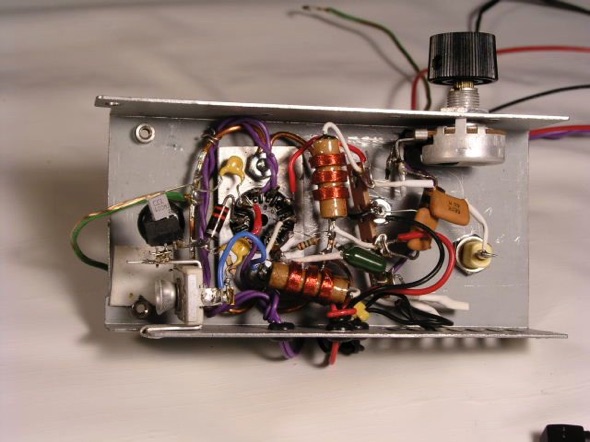
The original prototype was constructed on a sub-chassis salvaged from an old fax machine. The underside of the chassis is shown below:
How it works
The tetrode section functions as a modulated crystal oscillator
(Colpitts with cathode feedback), using the screen grid for
modulation. Both a quartz crystal and a ceramic resonator have been
used with good results. The value of C1 is 22pF when a quartz crystal
is used, and 150pF when a ceramic resonator is used. Also, when using
a ceramic resonator, it may be necessary to replace 100pF capacitor
C3 with a 10-100pF trimmer to fine tune the frequency.
Coupling from the tetrode plate to the antenna, in the original
prototype, was by means of a pi-network which was adjusted for
maximum power transfer. Pi-network component values depend on the
transmitter frequency, and antenna length and configuration. The
inductor had taps ranging from about 300 to 900 micro-henries in six
steps, which covered the medium wave band quite well when used with a
3 meter long antenna. When I created the original prototype, I was
still very inexperienced with the science of antenna matching, and
the highly adjustable pi-network allowed for a lot of adjustment.
However, it was not the most efficient for transferring power to the
antenna. When I designed the printed circuit board, I replaced the
pi-network with a parallel LC tank in the tube plate circuit, this is
simpler and more efficient. The parallel LC matching is shown in the
current schematics. For more information on both the pi-network and
the parallel LC matching, see the Antenna
Matching Page.
The triode section of the 6CQ8 functions as the audio pre-amp and
carrier control. It uses a fixed grid bias near zero volts (with no
audio input signal). There is no cathode bias. The significant point
is that the combination of the grid resistor, the input DC blocking
capacitor, and the diode action between grid and cathode, function as
a diode clamp which clamps the positive peaks of the audio input
signal to approximately ground potential. To be precise, due to
grid-cathode contact potential, quiescent grid bias is about -0.5
volts, positive grid current starts to flow at about this same
voltage, and so this is where the positive input peaks are clamped.
As a result, the grid bias is always equal to minus half the peak to
peak audio input level minus a half volt. It's important to point
out, that with this circuit, the term "quiescent" does not
mean "average DC level", as it often does in AC coupled
circuits, where the meanings are often interchangeable; it refers to
the state with no audio input signal. With varying input signal
levels, the average DC levels will shift. Consequently, the signal at
the plate will have its negative peaks near the quiescent DC plate
voltage, and the positive peaks will vary with the audio signal. The
average plate DC level will be proportional to the average audio
level. This average DC level on the plate is the desired carrier
control. By direct coupling the triode plate to the screen grid of
the tetrode, the combined audio and DC carrier control will modulate
the tetrode oscillator section of the tube. The predecessor to this
circuit, using the 6M11, required a DC level shift which was
accomplished quite simply by placing an NE-2 neon lamp between the
triode plate and pentode screen. However, no DC level shift is
required in the present design, further simplifying the circuit.
The quiescent point of the triode plate and tetrode screen is
chosen to be a relatively low voltage which still allows the tetrode
oscillator section to generate a modest carrier. As with the earlier
circuit, a variable resistance was initially provided in the plate
circuit to set this level. However after a considerable amount of
testing it was found that these could be replaced with a fixed 820 kΩ
resistor. All deviations from the quiescent point will be in the
positive direction, and accordingly, these deviations will increase
the RF signal output from the tetrode.
A printed circuit board has now been designed for this
transmitter. See the bottom of this page for the PCB design files.
I had the component silkscreen applied to both sides of the board to make it easier to mount parts on either side. I did this in order to allow for the tube to protrude through the top of the enclosure without the other parts getting in the way.
In the photo you can see that I used a small transistor radio IF or
LO coil for the plate inductor. It happened to have the correct
inductance adjustment range needed to match my antenna. Because of
the pin spacing, I had to make a small daughter board using a small
chunk of veroboard. Although these coils seem as if they’re too
small to handle the RF voltage that may appear across them, I haven’t
experienced any failures yet.
Performance
One must naturally wonder what a controlled carrier signal sounds
like at the receiver end. Without any AGC circuit in the receiver,
the effect would be much like an audio expander circuit, which is
often used in audio systems to provide a "presence" effect.
However, the AGC circuit in the receiver compensates by
re-compressing the audio, reducing (but not eliminating) this effect.
To eliminate the effect completely, the AGC loop gain would have to
be infinite, which of course, it is not. Therefore, there remains a
net expansion effect, which in my listening tests, I found to be a
pleasant departure from the usual heavily compressed audio of
commercial broadcast stations. I have to say that this is all
subjective, of course.
It is important though, that the time constant of the carrier
control, be compatible with the time constant of the receiver AGC.
The carrier control time constant is set by the triode grid resistor
and the input capacitor. In the present circuit the time constant is
100 milliseconds, which I found to be optimum in my tests, and
compatible with the AGC time constant in all receivers with which I
tested the transmitter. In fact, there is very little variation in
the AGC time constant between different receivers, because the
optimum value is a trade off between two constraints. It must be fast
enough to follow signal fading, and slow enough not to be affected by
the audio modulation. These constraints tend to put receiver AGC time
constants in the 100-150 millisecond range.
Another point to consider is the possibility of introducing some
distortion due to the triode clamp circuit. It would be expected that
positive peaks of the audio signal would cause a considerable
increase in grid current and therefore cause a drastic decrease in
input impedance at these peaks, leading to a flattening of the top of
the input signal waveform. This has proven not to be a problem. There
is no visible flattening of the input signal in the scope traces.
Very fast transients would be the most probable cause of distortion.
However, no distortion was audible to me during listening tests. An
audio expert, with better ears than mine, might argue otherwise, but
I'm quite happy with the audio quality.
One additional characteristic that this transmitter exhibits, is
inherent soft limiting at both the 0% and 100% ends of the modulation
envelope, which makes it difficult to overdrive it to the point of
audibly unpleasant distortion. This soft limiting is typical of
screen modulated transmitters, but it seems to work better with some
tubes than others. It works well in conjunction with the carrier
control to make set-up virtually foolproof.
Shown here is a trapezoidal trace of the transmitter modulation.
Appended to the right side is the amplitude of the unmodulated
carrier which is about 2.2 divisions on the scope. The maximum
amplitude is about 7 divisions, and the minimum amplitude is 0.2
divisions. From these numbers it's possible to calculate the upward
and downward modulation as follows:
MU=(7.0 - 2.2)/2.2 x 100 = 218%
MD= (2.2 - 0.2)/2.2 x 100 = 91%
The average of these is 154%
Following is a video showing trapezoidal scope traces for a short
musical excerpt*. The audio is the actual audio received on a nearby
receiver. The receiver has an IF bandwidth of 8 kHz which shows off
the fidelity of the transmitted signal.
*The musical excerpt:
Album: African Guitar Summit; CBC Records, 2004.
Artist: Alpha Yaya Diallo
Title: Cette Vie
If you liked the excerpt, then please buy the CD.
Antenna Matching Update
Please refer to this page for updated information about: Matching a
Part 15 transmitter to a short antenna br
It discusses the antenna pi matching network used in the original
prototype, as well as the simpler and more efficient antenna matching
network used in the final version.
Note that the Gerber files are for a double board, i.e., two
transmitters on a single board, because the overall size falls within
most fabricators’ 100mm x 100mm minimum charge size. As time
permits, I’ll add the Gerbers for a single board.
Back to: Projects Home
This page last updated: February 4, 2023
Copyright 2011, 2023, Robert Weaver


 Shown here is a trapezoidal trace of the transmitter modulation.
Appended to the right side is the amplitude of the unmodulated
carrier which is about 2.2 divisions on the scope. The maximum
amplitude is about 7 divisions, and the minimum amplitude is 0.2
divisions. From these numbers it's possible to calculate the upward
and downward modulation as follows:
Shown here is a trapezoidal trace of the transmitter modulation.
Appended to the right side is the amplitude of the unmodulated
carrier which is about 2.2 divisions on the scope. The maximum
amplitude is about 7 divisions, and the minimum amplitude is 0.2
divisions. From these numbers it's possible to calculate the upward
and downward modulation as follows: