Mini-Tube Audio Amplifier - Part 1
It would appear that there comes a time for every electronics experimenter where they feel the need to build a
tube audio amplifier. And so it has come to pass with me. For my first serious attempt, I decided to keep things
rather conservative—under 1 kilowatt. Well actually, under one watt per channel.

Warning:
This is not intended as a step by step DIY construction project. It's a discussion of my experience building
this project, and an explanation of the various design, construction and testing stages. I recognize that some
people may use this information to build their own version of this project. Consequently, take notice that
there are high voltages present in this circuit which can be lethal. These voltages are significantly higher
than those of other tube electronics projects which appear on this web site. Proceed at your own risk.
A discussion came up on one of the news groups some time ago about
building the smallest (or simplest) push-pull tube audio amplifier.
This got me thinking about making a one tube push pull amplifier (two
tubes for stereo). I had a few 6M11 Compactron tubes on hand that I
previously used to build this AM
transmitter.
 These tubes have a pentode section plus two
identical triode sections. I thought that the pentode would be a good
preamp, while the triodes would serve as the push-pull output. The
triodes are only rated for a maximum plate dissipation of 2.25 watts
each.
So, this is definitely a low power audio project (less than a watt RMS per channel). But, it seemed like a
good application to drive desktop speakers from a computer audio output. Just to keep things in perspective, here
is a picture comparing the size of a 6M11 with the well known 6SN7GT. As you can see, this is a rather tiny tube,
considering that it comprises three sections.
Using the pentode section as a preamp, and the triodes as the output stage, there's no section left to act as a
phase inverter. There are other options however. Some of the earliest designs fed the push-pull output stage from
a centre tapped inter-stage transformer which accomplished the phase inversion task. However, I decided that
inter-stage transformers are a rather dated design technique. Instead, I decided to drive one half of the
push-pull output directly from the pentode preamp stage, and then use the plate signal from the first triode to
drive the second triode. To do this, the triodes must not be cut off for any part of the input cycle. In other
words, they must operate in Class A mode. This isn't a big deal, because the reduced efficiency of Class A mode
makes little difference at these low power levels.
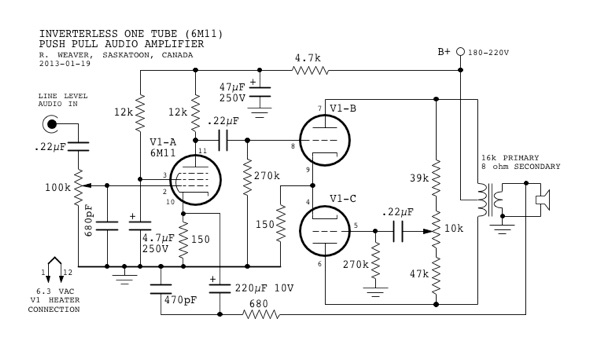
This is the prototype circuit:
Click for a larger View
And here is the original breadboard assembly:

The output transformer has its primary taps wired to a 2 pole
multi-position rotary switch in order to test different impedance
ratios on the fly.
The Preamp Stage
The preamp stage is a standard cathode biased amplifier stage. The
cathode resistor is not bypassed, because this stage already has
sufficient gain, and by leaving the cathode resistor unbypassed, it
provides a means to introduce negative feedback later. The voltage
gain is approximately equal to the plate load resistor divided by the
cathode resistance, or:
Av
= 12000 / 150 = 80
Note
the 680 pF shunt capacitor at the input. I added this after
discovering that many digital audio sources have insufficient
filtering, and include sampling frequency noise components at around
44 kHz. I didn't want this passing through the amplifier. This low
value capacitor removes the high frequency noise without affecting
audio frequency signals.
The Push-Pull Output Stage
I
mentioned that the inverted input to the second output triode would
be taken from the plate of the the first triode. In fact, this is
only partially true. Because the two triode sections share a common
unbypassed cathode resistor, the output stage acts as a cathode
coupled differential amplifier. However, because of the relatively
low value of cathode resistor, the cathode current will not be
constant as it would in a normal differential amplifier (rather than
the traditional 'long-tailed pair', we have, so to speak, a
'short-tailed pair'). Therefore, the cathode drive to the second
triode will not produce an equal plate swing. In a normal cathode
coupled stage, the grid of the second triode would be grounded.
However, in this circuit, the grid of the second triode receives a
small amount of signal from the plate of the first triode to
compensate for the insufficient cathode drive.
The
potentiometer in the voltage divider shown on the right side of the
diagram is adjusted to get the proper level of inverted signal to
drive the grid of V1-C. One interesting thing to note, is that this
voltage divider must connect to the opposite ends of the output
transformer, rather than from V1-B plate to ground. This is because,
in the latter case, there would be a positive feedback effect which
makes the stage unstable. This happens because, as the plate of V1-B
goes more negative, causing the grid of V1-C to go more negative, the
plate of V1-C then goes more positive, and because of the coupling
between V1-B and V1-C plates due to the autotransformer effect of the
output transformer primary, this causes the plate of V1-B to go even
more negative. Hence, the positive feedback situation, and adjustment
of the V1-C drive potentiometer is very touchy. By connecting the
lower leg of the drive potentiometer to the V1-C plate, this
introduces a slight negative feedback to counter the positive
feedback. Adjustment of the drive pot, is then much smoother.
Up
to this point, circuit component values and power supply voltage were
selected based on a preliminary load line analysis using a slightly
modified single ended loadline. This was fine for determining
quiescent operating plate voltage and current and grid bias, but not
ideal for determining plate dissipation, output impedance matching or
power output. For that, composite plate curves are needed. However,
they are laborious to produce manually, and must be completely redone
whenever the operating point changes.
During
this time, I had been doing some research on vacuum tube SPICE
models. It appeared to me that at the present time the most accurate
triode model is the one given on
Norman Koren's Site.
His plate current formula is:
IP
= (E1X/kG1)(1
+ sgn(E1))
where the value E1
is given by:
E1
= (EP
/kP)
log(1 + exp(kP(1/µ
+
EG
/sqrt(kVB
+
EP2))))
where
EP
is plate voltage, EG
is grid voltage, and the remaining variables kP,
µ,
x,
kG1
and kVB
are constants which depend on the tube characteristics.
The sgn() function returns +1 if the argument is greater than zero,
and −1 if the argument is less than zero. By tabulating
the data from the published 6M11 triode plate curves, entering them
into a spreadsheet, and then performing a multi-variable
optimization, I was able to determine the values of the constants to
be:
µ
=
84.8
x
=
0.98
kG1
=
162.87
kP
=
243.8
kVB
=
2664.39
Using these values, Koren's triode formula models the published triode
plate curves very precisely. In fact, manufacturing variations
between tubes would create deviations greater than those of the
model. Rather than model the circuit in SPICE, I chose to use the
spreadsheet to create the tube curves and load lines. In creating the
load line, I used the original circuit component values, and then
refined them during the analysis. A graph based on adjusted component
values is shown below:
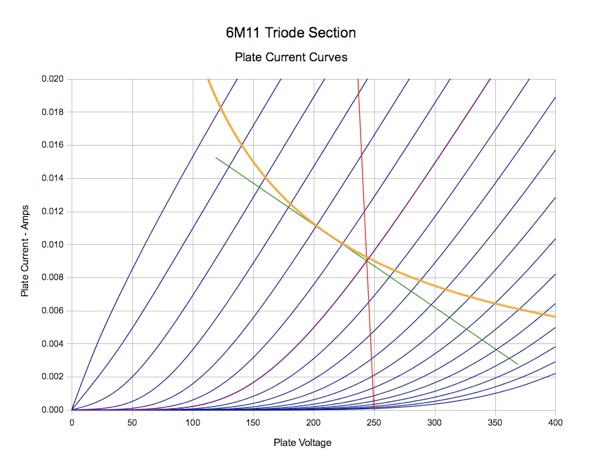
The blue lines are Plate Current vs. Plate Voltage for grid voltage
increments of 0.5 volts for each curve. Normally, the first curve on
the left is 0 grid volts, and then each curve increases in round
numbers. However, this graph has the grid voltages shifted slightly
so that one of the curves (violet) will pass exactly through the
quiescent operating point. In this case, it corresponds to a grid
bias of −2.84
volts. The curves moving away from the violet one change by
increments 0.5 volts, in order to preserve linear display of the I-V
characteristics.
The red line is the static load line, and the green line is the dynamic
load line.
The
orange line is the locus of maximum allowable plate dissipation which
is 2.25 watts for the 6M11 triode section. To stay within the tube's
allowable ratings, the quiescent point must be below this line, and
ideally the entire dynamic load line should remain under the this
line as well. However, as long as most of the dynamic load line
remains below the maximum dissipation line, the average power will
generally be less than the maximum, and this is acceptable. That
didn't appear to be a problem in this situation, because the dynamic
load line just touches the maximum dissipation line at one point and
otherwise remains in the safe area. It can be seen immediately that
the original plate supply of 180-220 volts has been increased to 250
volts. The static load line includes a cathode bias resistance of 160
ohms plus transformer primary winding resistance of 350 ohms. When
creating the load line for one tube, because the cathode resistor
will be shared by two tubes, its value must be doubled. Hence the
total DC load resistance will be 160x2+350=670 ohms.
From
the analysis, the quiescent operating point gives a plate voltage of
244 volts, plate current of 9 mA, and a quiescent plate dissipation
of 2.2 watts. As mentioned previously the grid bias is −2.84 volts.
It
became apparent that the dynamic load of 16k was a bit too low, and
so it was changed to 20k. Fortunately, I had another output
transformer available with a 20k primary.
An
advantage of having an accurate plate current formula in the
spreadsheet is that composite push-pull plate current curves can be
generated.
Following
is the set of composite characteristic curves:

Again, the central violet curve corresponds to the chosen grid bias of −2.84
volts. Each curve moving away from the central one has an incremental
grid voltage of ±0.5
volts.
Note how the combined plate curves show amazingly good linearity, both in
the even spacing between curves (indicating constant gain over over
the full dynamic range), as well as constant slope of the curves
(indicating a constant output impedance over the full dynamic range).
It should be mentioned that the first two and last two curves have
positive grid voltage (+0.16V and +0.66V) on one of the triodes. My
past experience shows that these triodes draw very little grid
current when positively biased, and it can be seen here that as long
as the tube model is still accurate in this region, then linearity
continues to be very good.
Maximum
power output is achieved when the slope of the dynamic load line
(green) is the reverse of the slope of plate curves. It can be seen
that this is the case, with the chosen load impedance of 20k.
Maximum Plate Dissipation Curves
Whereas
generating the composite plate current curves was relatively
painless, calculating the maximum plate dissipation locus turned out
to be quite a challenge. It's easy to do on the single ended curves,
as one simply plots the line I=PMax/V.
However, on the composite curve graph, the current axis is
differential current and there is no direct way to determine the
maximum differential current given a plate voltage value. The
solution involves tracing along each composite curve to find the
point where I
×
V
for
a single tube is equal to PMax,
and then recording that point. This is repeated for each curve, and
then a line is drawn through all of these points to produce the
maximum plate dissipation curves. Doing this on a spreadsheet
requires a lot of calculation cells and is a bit messy, but it can be
done. The result of all this is the following composite curves which
include the maximum plate dissipation lines (in orange). The upper
line indicates the upper limit for the upper tube, and the lower line
indicates the lower limit for the bottom tube. The safe operating
range is the band between the orange lines. To avoid exceeding
maximum plate dissipation ratings, the dynamic load line should be
between these two limits.
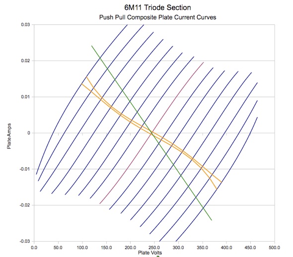
Not good! Obviously, I did a poor job picking the operating point. The
good thing is that the composite curves immediately reveal the
problem. At this point I decided to reduce both plate voltage and
plate current, and try again. The advantage of having everything on a
spreadsheet is that the results of any change are immediately
displayed. Here is the next attempt using a plate voltage of 240
volts and plate current of 7 mA:
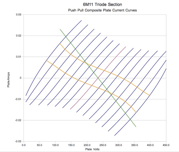
This is better, but at high output levels the maximum allowable plate dissipation of each triode will still be
exceeded part of the time. By increasing the load impedance to 30,000 ohms, the dynamic load line can be made to
fit within the allowable power band as shown in the next graph below:
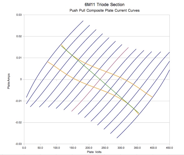
This shows a voltage swing of 240 volts peak-peak into the 30k load which gives an output power of 0.24 watts RMS,
which is less than I'd been hoping for. In the end, partly because I didn't have a 30k output transformer, I opted
for the design shown in the previous chart which gives 0.36 watts, and stays within the maximum dissipation
ratings on average.
Having nailed down the basics of the amplifier, I decided to add some refinements. These are discussed in the next
few sections.
Negative Feedback
From initial testing, the amplifier has a reasonable frequency response (considering the inexpensive output
transformer) of 25 Hz to 15 kHz, and reasonably low distortion. However, the amplifier has plenty of gain, and it
makes sense to take advantage of the excess gain, and introduce some negative feedback to improve frequency
response and further reduce distortion. There are several ways to incorporate negative feedback. The method I
chose was to take the output signal from the output transformer secondary back to the cathode of the pentode
section.
Adding negative feedback to a high gain amplifier introduces the risk of instability, and the possibility of the
amplifier breaking into oscillation. This happens because certain reactive circuit components cause phase shift,
and at certain frequencies the combined phase shift can reach 180°, at which point the amplifier becomes an
oscillator. Most of the phase shift comes from the output transformer, generally at high audio or ultrasonic
frequencies. There are a couple of methods to prevent this from happening. The first is to add a parallel RC
network, in the feedback path, which has a complementary phase shift characteristic thus reversing the phase shift
introduced by the output transformer. The second method is to add an RC low pass filter, in the feedback path,
which rolls off the feedback to a sufficiently low level at higher frequencies so that at the point where the net
phase shift reaches 180°, the total loop gain is less than one, and oscillation is not possible. This second
method is the approach that I used. The 470 pF capacitor in combination with the feedback resistor (680 ohms in
the above schematic diagram) accomplishes the feedback roll-off.
With negative feedback applied, the 3db frequency response is now 20Hz to 70 kHz.
Tone Control
I decided that the amplifier needed a tone control. I wanted something
better than a simple adjustable RC low pass filter, but at the same
time, wanted to stay with a single knob control. It must be a passive
circuit, since I've already used up all the tube sections, and the
tone control must be outside of the negative feedback loop. This
means that it has to be right at the input, or else at the speaker.
(Tone control at the speaker has been done, but requires some odd
component values.)
After a bit of web searching, I found two particularly interesting tone
control circuits:
Derek
Bowers simple tone control article in EDN (Electonic Design News)
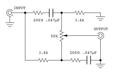
His circuit is shown below:
Frequency Response of the Bowers' tone control:
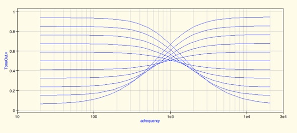
The Bowers circuit looks very good. Bass boost and treble cut at one end
of rotation, and then treble boost and bass cut at the other end;
completely flat at mid-rotation, and very significant amounts of
boost and cut at the end positions. In addition, the circuit is very
simple.
The only problem is that it requires a very low impedance signal source
(<200 ohms), and a very high load impedance. The high load
impedance is normally not a problem with a tube, but I still need a
volume control, and that means something in the 500k range in order
not to load down the tone control output. Using high resistance
volume controls can lead to increased hum and noise though. I also
found that some of my audio input sources have significantly higher
impedance than 200 ohms, which would therefore require an additional
buffer stage prior to the tone control.
I
didn't immediately rule out the Bowers' tone control, but decided to
look at some tone controls that were specifically intended for tube
amplifiers.
The
next one that I looked at is Simcha
Delft's 'Moonlight' tone control.
The circuit is shown below:
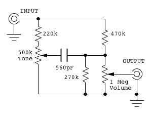
This one is intended for a tube amp, and has component values more in line
with what I was looking for. It also allows for (and includes) the
volume control. The 1 Megohm volume control resistance is higher than
desirable, but the 270k fixed resistor and 1 Meg. pot can be replaced
with a 250k pot. Additionally, all of the component values can be
scaled down to more acceptable ones without affecting frequency
response.
Unlike the Bowers circuit, this circuit only gives treble boost/cut, and
leaves the bass unaffected.
Frequency Response of Simcha Delft's 'Moonlight' tone control:

That may not be such a big deal since everything is relative, but the
treble boost/cut is about half the range that the Bowers circuit
gives. So relatively speaking the overall effect is the about 1/4 of
the former circuit. Furthermore, since this circuit doesn't give a
complementary bass cut/boost, the tone control affects the perceived
overall volume.
Since I'd been running simulations of both of these circuits anyway, I decided
to experiment with different configurations. I eventually came up
with another bridge circuit, somewhat different from Delft's:
My bridge tone control:
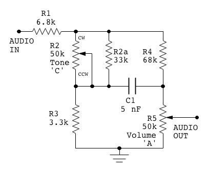
Interestingly, by adding the input resistor, changing the tone potentiometer to a
two wire variable resistor configuration, and changing other
component values, the circuit gives bass boost and treble cut at one
end of rotation, and bass cut and treble boost at the other end of
rotation. Though the total amount of boost/cut is equal for bass and
treble, using a linear taper control, it can be seen from the
following frequency response graph that the control adjustment
characteristic is not linear.

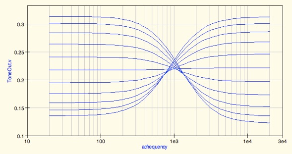
Each curve on the graph is an equal increment of tone control resistance. The control characteristic falls
roughly halfway between linear taper and reverse audio taper. However, by paralleling a fixed resistance with an
audio taper control, the control action becomes much more linear, and gives flat response at mid position, as
shown in the next graph where each curve is an equal increment of control rotation:
The final tone control circuit is shown below:

As previously mentioned, for a proper linear control characteristic, the
tone control must be a reverse audio taper (also known as C-taper) or
else a standard audio taper control must be wired so that bass
increases with clockwise rotation, and treble increases with
counter-clockwise rotation. I decided to use a standard audio taper
control, and live with the reverse operation (and redesignate it as a
bass control).
If the constructor is not concerned about having the flat response
exactly at mid rotation, then a 20k or 25k linear taper control (in
place of the 50k pot & 33k fixed resistor) gives perfectly
acceptable performance. My personal preference was to have flat
response at mid-rotation (making it easier to do frequency response
testing among other things), so I went with the audio taper
arrangement.
This tone control is not as fussy about input signal impedance as long as
it doesn't begin to approach the value of R1.
Also, the tone control and volume control are identical in value
which helps in sourcing parts.
There are always compromises though. The boost/cut ratio is slightly higher
than Delft's circuit, but still only about a third of the Bowers
circuit.
Here is a summary of the tone control characteristics:
-
Frequency
response is flat when R2/R3
=
R4/R5
(ie., the bridge is balanced, hence no current passes through the
capacitor which is the only reactance in the circuit). With the
component values given, R2
(actually, the net value of R2
in parallel with R2a)
is adjusted to 4.5k for flat response. That works out to be
mid-position for an audio taper pot.
-
For
equal boost and cut range, the R2
value should be about 8 times the R3
value.
-
For
equal treble and bass adjustment range, R1
should be equal to R2+R3
(when R2||R2a
is set to flat position: 4.5k). To be more precise, R1
should be equal to the combined resistance of the parallel
combination of
(R2+R3)||(R4+R5),
but since R4+R5
is much greater than R2+R3,
it doesn't affect the value significantly.
-
Doubling
R1
makes the bass boost/cut range double the treble boost/cut range.
-
Likewise,
halving R1,
halves bass boost/cut range relative to treble range.
-
For
the resistance values shown, the C1
value is determined from the desired crossover frequency, FC,
according to: C1=0.005/FC,
where capacitance is in microfarads, and frequency is in kilohertz.
So, a 0.005 µF capacitor gives a crossover frequency of 1 kHz.
Though
1 kHz crossover frequency seems to be standard in most of the tone
controls I've seen, I find this a bit high for my taste, and I opted
for a lower frequency using a capacitance of 0.0068 µF
resulting in a crossover frequency of 735 Hz.
One
rather useful thing about this circuit (as with Delft's) is that
since the crossover frequency is set by a single capacitor, different
values can be switched in, to change FC.
Continue to Part 2
Back to:
Projects
Home
This page last updated: February 9, 2023
Copyright 2015, 2023, Robert Weaver
 These tubes have a pentode section plus two
identical triode sections. I thought that the pentode would be a good
preamp, while the triodes would serve as the push-pull output. The
triodes are only rated for a maximum plate dissipation of 2.25 watts
each.
So, this is definitely a low power audio project (less than a watt RMS per channel). But, it seemed like a
good application to drive desktop speakers from a computer audio output. Just to keep things in perspective, here
is a picture comparing the size of a 6M11 with the well known 6SN7GT. As you can see, this is a rather tiny tube,
considering that it comprises three sections.


