3-Tube AM Stereo Transmitter

I think that a sizeable percentage of the people reading my web pages
probably assume that I'm one of those crazy people who believes
vacuum tubes are superior to solid state devices. That's not true
(except maybe the crazy part). I like vacuum tubes because it's fun
and challenging to build circuits using this old technology. It
forces the designer to analyse the circuit requirements carefully,
and to come up with a minimal optimum design. With solid state, you
can throw a few hundred transistors at almost any problem in order to
solve it. You can't do that with vacuum tubes, so you have to come up
with a good basic design. Therein lies the challenge.
For some time, I've contemplated building an AM-Stereo transmitter using only
vacuum tubes, and of course, the fewer, the better. Remarkably, as I
will demonstrate, a good quality low power AM-Stereo transmitter can
be built using only three vacuum tubes.
AM Stereo in a Nutshell
AM stereo
broadcasts began in the USA, Canada, Australia and Japan in the
1980's. Initially, there were several different incompatible systems:
Belar, Harris, Kahn, Magnavox and Motorola. All were based on
variations of angle modulation of the carrier with the L-R stereo
difference signal, and then the resulting signal is amplitude
modulated with the monaural L+R signal, making the signal compatible
with existing monaural receivers. This also made it reasonably simple
to upgrade existing broadcast stations by replacing the existing
crystal controlled exciter with an angle modulator unit, which was in
the low power section of the transmitter. The high power amplitude
modulator could be left essentially unchanged. In fact, the biggest
cost usually was in upgrading the audio signal chain from mono to
stereo.
Eventually, the Motorola C-Quam system won out and became the standard for
AM-Stereo. Over the years, there has been much politically charged
debate about the merits of the different systems. I don't intend to
get involved with that debate here. However, for the purpose of
explaining the following design I will briefly discuss some basic
similarities and differences of the Magnavox and Motorola systems.
The Basic Transmitter Design
The Magnavox system is the simplest system, in that the L-R angle
modulation, is just a linear phase modulation scheme. The Motorola
system, although its full name is 'Compatible Quadrature Amplitude
Modulation', it's simply a non-linear phase modulation scheme. The
Motorola system uses a lot of circuitry to quadrature modulate the
L+R and L-R signals onto the carrier, and then passes the resulting
signal through a limiter, which after going to all that trouble,
leaves just a phase modulated signal. So why bother? To answer that
question would require that we get involved in the politically
charged debate. Suffice to say, the difference between the linear and
non-linear phase modulation is not significant except in certain
special cases such as when an audio signal appears only in one stereo
channel at high amplitude. Statistically, this happens rarely in most
normal music. For more normal conditions, the output of the C-Quam
phase modulator is a reasonably linear function of the L-R signal.
For that reason, it appeared to me that the design of a C-Quam
compatible transmitter could be greatly simplified by using a simple
linear phase modulator circuit. In subsequent tests, I confirmed
this. Even when using the worst case audio signals, although there
would theoretically be some distortion in the received audio, this
distortion was not audible.
To proceed then, I needed to come up with a simple phase modulator, a simple
amplitude modulator, and simple audio matixing circuitry. A further
requirement is a pilot tone generator. For the C-Quam system, this is
a low level 25 Hz tone which tells the receiver that a stereo signal
is present.
The audio matrixing combines the left and right audio inputs to create the L+R
and L-R audio signals. This is easily accomplished using audio
transformers with dual secondary windings, and then by connecting the
secondaries as series aiding to get the L+R signal, and series
opposing to get the L-R signal.
For the amplitude modulator portion of the circuit, I decided to reuse most
of the circuit from The
Improved 1-Tube AM Transmitter. It is very simple and works well.
That leaves only the phase modulator part of the circuit. After doing a
bit of research, I decided to go with a reactance tube phase shift
circuit. Actually, when restricted to vacuum tube circuits, there
isn't a lot of choice in the matter.
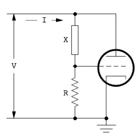 It's worthwhile discussing the
basic reactance tube circuit in a bit of detail,
because its principle of operation is not immediately obvious, and it is a very
critical part of the transmitter circuit. The diagram shown here is
the most basic reactance tube circuit. Assume that an alternating
voltage V is applied to the terminals on the left hand
side, as shown. The component X is a pure
reactance—either capacitive or inductive. Also assume that the
reactance X is a high value so that relatively little
current flows through it. Therefore, most of the current I will be
due to the plate current of the tube. The plate current of a vacuum
tube is given by the following relationship:
IP = gmVG
Where
IP is plate current, gm is the
tube's transconductance, and VG
is the grid voltage. The grid voltage is proportional to the current
through the resistance R which in turn is equal to the
current through the reactance X. Since the current
through a reactance is 90° out of phase with respect to the voltage
across it, the grid voltage VG
will be 90° out of phase with respect to the terminal voltage V,
and consequently, the plate current will be 90° out of phase with
respect to the terminal voltage V. Since this reactive
current is also proportional to the tube's transconductance, if the
transconductance changes, then the reactive current also changes. As
it happens, a tube's transconductance is a function of the grid bias
voltage, so that if we change the grid bias, then the reactive
current can be changed. Thus,
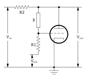 we have at the terminals, effectively, a variable reactor which can
act as either a variable capacitance or variable inductance,
depending on the component choice for X. This variable
reactance can be combined with an additional resistance (R2
in the diagram as shown at the left) to make a simple phase shifting
network. Here, the modulation voltage VMOD,
controls the grid bias and hence the transconductance and phase
shift. While this very basic circuit would work after a fashion, it
has a number of drawbacks. One of the most serious is that the output
amplitude varies with the amount of phase shift. Almost as simple,
but without these drawbacks, is a reactance tube phase modulator
circuit from F.E. Terman, Electronic and Radio Engineering, 4th
Edition, McGraw-Hill, 1955, page 604. It is shown below.

The details of powering the
circuit and biasing have been omitted in this simplified drawing.
Terman gives only a very brief discussion of the circuit, but
attributes it to S.M. Beleskas, Phase Modulation Circuit,
Proceedings of the National Electronics Conference, Chicago, Vol. 3,
1947, pages 654-661, where an in-depth analysis is given.
The components marked X, are reactances of equal value.
They may either be both capacitive or both inductive.
VIN
is the RF carrier input signal which is to be phase modulated. VOUT
is the phase modulated carrier output. I won't give a detailed
analysis here, but its main advantages are:
The
phase shift of this circuit is given by the following formula:
ø = 2
Arctan |X gm|
where
ø is the phase shift, X is the reactance
indicated in the schematic, and gm is the vacuum tube
transconductance.
Given
the Arctan function, it's immediately obvious that the phase shift
will be a rather non-linear function of the transconductance. The
following graph of phase shift vs. transconductance confirms this.
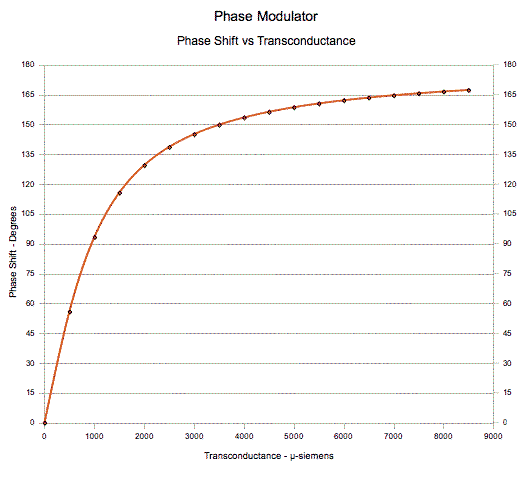
All is not lost, however. As
it turns out, a tube's transconductance is a non-linear function of
grid bias. Following is a set of transconductance curves from the
General Electric Vacuum Tube Guide for the tetrode section of a 6CQ8
triode/tetrode.
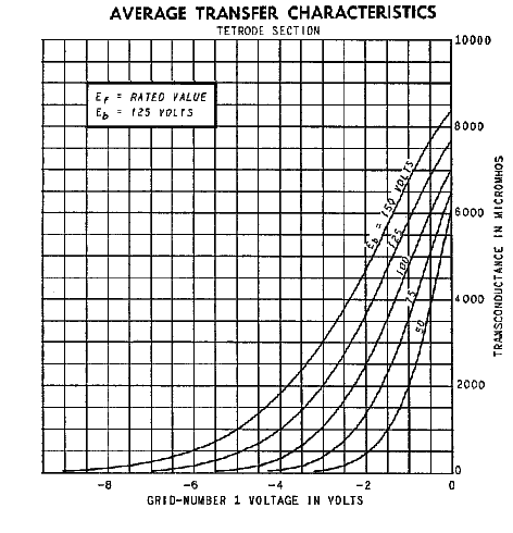
It can be seen that these
curves bend in the opposite direction to the phase shift curve. So,
by choosing the appropriate screen voltage and grid bias, it may be
possible to linearize the phase shift function over some useable
range. The data from the transconductance curves were entered into a
spreadsheet table, and then applied to the phase shift function.
Using 100 pF capacitors for the reactors, and an operating frequency
of 1500 kHz (giving a reactance X of 1061 ohms), and a screen
voltage of 75 volts, the results are plotted on the chart below.
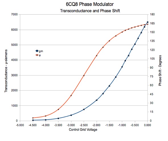
The blue curve is the
transcribed transconductance curve for a screen voltage of 75 V. The
red curve is the resulting phase shift as a function of grid bias. It
can be seen that with a grid bias of−2.5 volts, the phase shift is
quite linear over the range of ±45° which is sufficient for the
present application. (For a C-Quam compatible transmitter, we don't
need any more than ±30° phase shift.) Just to clarify, with a bias
of −2.5 volts, the quiescent point is a nominal phase shift of 75°,
and with suitable grid modulation, can vary from 30° to 120°
without becoming significantly non-linear. The fact that the
quiescent phase shift is 75° rather than 0° is immaterial, because
all that matters is the phase shift relative to the quiescent point.
The S-shape of the curve is also an advantage, because it partially
compensates for the non-linearity of the C-Quam phase modulator when
large stereo difference signals occur.
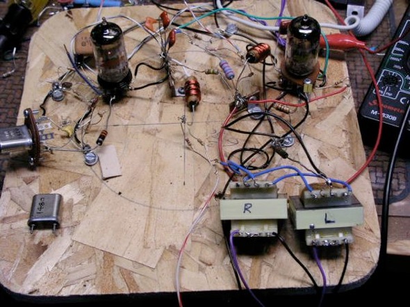
Having
found a suitable candidate for the phase modulator, it was time to
put together a prototype circuit. The prototype was built breadboard
style on a piece of wood as shown below:
Here is the original prototype schematic.
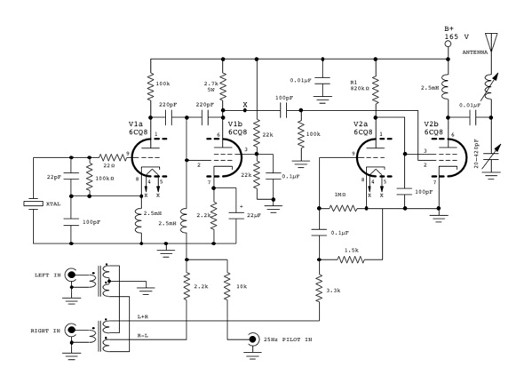
Click for a larger View
In this circuit, V1a is a
crystal oscillator which generates the carrier signal. It is a common
Colpitts type crystal oscillator. V1b is the phase modulator.
Although a triode was shown in the simple circuits discussed earlier,
the tetrode is preferable in this application. In a triode, the
transconductance will vary with plate voltage, which is undesirable.
In a screen grid tube, transconductance is reasonably immune to plate
voltage variations. The 220 pF capacitors connected between the
plates of V1a and V1b perform the function of the X
reactors previously discussed. During testing of the prototype, the
value of these capacitors was changed a number of times. During early
testing, the 220 pF capacitors gave best performance, but with
further circuit adjustments, a value of 100 pF was eventually chosen
as the best value for the chosen operating frequency of 1500 kHz.
However, there is a lot of leeway in the chosen values. I was able to
switch operating frequency from 1500 kHz to 1000 kHz without changing
the capacitor values, and only a minor V1b bias adjustment was
necessary. Though, if designing the transmitter for a specific
frequency, I would recommend choosing capacitors to give a reactance
of close to 1000 ohms at the operating frequency.
V2a
and V2b perform the same controlled carrier amplitude modulation
function as previously described in The
Improved 1-Tube AM Transmitter. The only difference is that the
modulator section is not self oscillating. It receives the carrier
signal (already phase modulated) from the output of V1b. The L+R
modulation signal must be attenuated slightly to stay balanced with
the phase modulator input. This is accomplished with the 3.3k/1.5k
voltage divider between the audio input transformers and the V2a
grid.
For
initial testing, the pilot generator function was provided by an
external signal generator. The pilot tone is combined with the stereo
difference signal which is then used as the modulation signal for the
phase modulator. The pilot tone does not appear in the amplitude
modulated portion of the signal. During testing, it was found that
the left and right channels were reversed in the received signal.
This is actually good news, as it indicates that the receiver was
detecting a stereo signal and except for the reversed channels, was
decoding it correctly. It turns out that the phase modulator is
reverse acting, and requires an R−L signal instead of an L−R
signal. This was easily fixed by changing the secondary connections
on the audio transformers.
Here
are two audio files transmitted from the prototype transmitter, and
as received on my Sony ST-JX450A AM-Stereo receiver:
Soundclip:
Johnny Favourite Swing Orchestra
Towards
the end of this sample, I unplugged the Right audio input to the
transmitter for a few seconds, then plugged it back in and unplugged
the Left audio input. You can hear some faint but noticeably
distorted audio on the unplugged channel. This doesn't surprise me;
in accordance with theory, the worst distortion should occur when
there is only one channel present.
Soundclip:
Leftfield, Original
I
encountered some interference on my receiver while making these
clips. However, after I recorded the first one, I managed to adjust
the receiver's loop antenna to minimize the noise. So, the second
clip is cleaner.
One
other problem encountered in testing the prototype was that the
centre (L+R) channel audio was shifted slightly over to the right of
centre. While not overly offensive, it is audible in the above sound
clips, and I felt that it needed to be addressed. After a bit of
analysis I determined that if the carrier had any second harmonic
content, this would have the identical effect of an off-centre
signal, and consequently, the receiver was decoding it as such. It
appeared that there were two separate sources of 2nd harmonic
distortion. The first was in the crystal oscillator, and the second
was due to the carrier input to the phase modulator being at a high
enough level that it was causing self-modulation. The solution to the
oscillator distortion was to add an LC low pass filter between the
oscillator output and the input to the phase modulator. However,
fixing the self modulation problem in the phase modulator was not so
easy. It would require attenuation of the RF input in order to run at
a lower level, which would then require another stage of
amplification afterwards. Fortunately, there was an easier fix that
didn't require any additional tubes. It is possible to eliminate the
shifted audio simply by adjusting the tuning of the antenna matching
network.
There
is another possible method to eliminate distortion that I have
considered, but haven't yet tried. It occurred to me that if the 2nd
harmonic distortion of the oscillator could be made equal and
opposite to that of the phase modulator, then it would cancel out.
This could be done by inverting the output of the oscillator before
going into the phase modulator. This inversion could be done using a
1:1 inter-stage transformer, so that additional tubes would not be
required. At some point in the future, I may revisit this method, and
see how it works. For the present though, the antenna network
adjustment method is completely satisfactory.
With the prototype circuit working well,
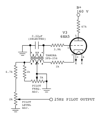 I decided to build a 25 Hz
pilot tone generator. I used a 6HA5 triode for no particular reason
other than the fact that I had some on hand. An LC resonant circuit
was chosen due to its high Q and good stability compared to other
types of low frequency oscillators. The inductance being supplied by
a small 1.1 VA power transformer (Tamura 3FD-256). Feedback is taken
from the cathode.
Fine tuning of the
pilot frequency is done by placing a variable load (using a 5k
potentiometer) on one of the transformer windings which, due to the
non linearity of the iron core, causes a change in inductance. With
the component values that were chosen, the adjustment range is
roughly ±3 Hz, which makes it very easy to get the required precise
adjustment. Most specifications for decoder chips require the pilot
to be 25 Hz ±0.6 Hz.
 This oscillator can easily maintain this accuracy even with an
unregulated power supply. However, because of the small adjustment
range, the tank capacitor must be hand picked to get near the centre
of the adjustment range. Fortunately, given the inductance of the
chosen transformer, the required capacitance conveniently happens to
be the standard value of 0.22 µF. As shown in the scope trace, this
oscillator produces a reasonably clean looking sine wave output that
doesn't require any additional filtering.
The complete final
schematic is shown below. (Click on it for a larger version, which
includes an additional multi-function metering circuit.)
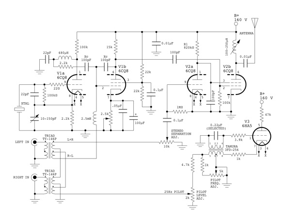
Click for a larger View
Some differences between the preliminary schematic and the final:
-
Trimmer
capacitor added to the crystal oscillator tank. This was done in an
attempt to reduce the 2nd harmonic distortion. It didn't help the
distortion problem, but it did turn out to be necessary if a ceramic
resonator is used instead of a crystal, as it provides fine
frequency adjustment.
-
V1b
cathode bias resistor replaced with a potentiometer to allow bias
adjustment.
-
Addition
of 680 µH/22 pF LC low pass filter between V1a output and V1b
input. This was described above.
-
Replacement
of the fixed L+R audio attenuator with a 10k potentiometer. This
allows optimum stereo separation adjustment.
-
Inclusion
of integral 25Hz pilot tone generator, as previously described.
-
Injection
of 25Hz pilot tone is now in series with R-L difference signal. This
eliminates the previously used resistor network, and maximizes the
amount of R-L modulation signal.
-
Replacement
of the antenna matching L-network and V2b plate choke with a simpler
adjustable inductive plate load (a small slug tuned coil from my
junk box) which forms a parallel LC circuit in conjunction with the
antenna capacitance. This is simpler, and gives lower losses
compared to the earlier circuit. The value of this inductor depends
on the antenna length and operating frequency.
-
Addition
of a multi-function meter (shown only on the larger schematic) which
is used to display audio input level (L+R), antenna network peaking
(diode detector RF probe placed in close proximity to RF output
lead), V1b cathode bias voltage level.
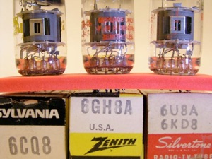
It’s also worth mentioning that while this circuit was designed
around 6CQ8 tubes, I've also tested it with 6GH8A, 6U8A/ECF82 and
6KD8 tubes, which all function identically, with no other circuit
changes required. Interestingly, the 6CQ8 is described by the
manufacturer, as a triode/tetrode while the others are described as
triode/pentodes. In fact, they are all beam tubes, and their internal
structures are identical.
The power supply circuit is shown below.
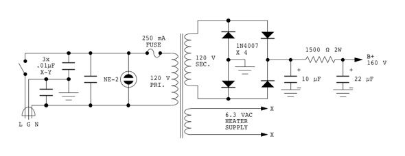
The power transformer is a 20 VA, 120 V isolation transformer removed from an old Razor Outlet. I added a 6.3 V
heater winding consisting of 46 turns of #24 AWG wire (0.5 mm) wound over top of the existing secondary winding.
The three 0.01 µF X-Y safety capacitors connected across the AC line are important in eliminating 60 Hz hum from
the signal at the receiver, because they prevent RF from travelling back through the power mains and causing hum
modulation via the receiver's power supply. The fuse shown in the power supply is actually a self-resetting
thermal circuit breaker built into the transformer.
Final Construction
|
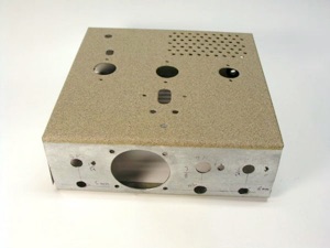
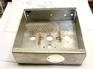
I constructed the chassis from a piece of 0.5 mm galvanized steel. This is a bit on the thin side, and
subject to warping. As a result, it wasn't appropriate to have a high gloss finish. So, I used a textured
matte "Stone" finish paint. Ventilation holes have been drilled for air circulation around the power
transformer.
|
|
|
|
Here is the underside of the chassis. The two terminal strips have been soldered in place to minimize the
number of screws visible from the top of the chassis.
|
|
|
|
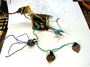
Because the chassis is quite compact, I set out to pre-assemble as many things as possible before
installing in the chassis. Shown here are the power transformer, power line filter, B+ rectifier and
filter, and tube heater wiring.
|
|
|
|
The audio and pilot oscillator transformers were designed for printed circuit mounting. So, it was most
convenient to build several pre-assemblies using veroboard. These are shown here, along with the
pre-assembly for the crystal socket (made from perf-board and a 9-pin miniature tube socket), and the
mounting bracket for the antenna tuning coil.
|
|

|
|
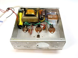
Here, the power transformer, B+ supply, tube sockets, and antenna tuner are installed.
|
|
|
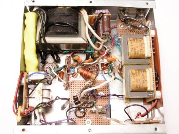
And finally, the photo below shows the underside of the completed chassis.
|
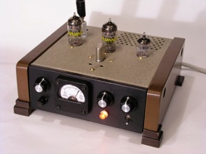
The cabinet was completed with the addition of front and side panels of MDF (medium density fibreboard). The side
panels were stained with medium walnut stain and finished with lacquer. The front panel was painted black. Note
that the completed unit is quite small 150 mm (6") square, by 50 mm (2") high, excluding the side panels.
|
|
|
Checkout and Set-up Procedure
Set-up of the completed transmitter
was fairly easy, having already worked out most of the bugs with the
prototype. Although there are quite a few things to adjust, they can
all be significantly out of adjustment, and the transmitter will
still put out a signal. The procedure that I used is as follows:
-
Connect the antenna, turn on the power, and allow a few minutes for
the tubes to warm up and temperatures to stabilize.
-
Ensure the main crystal oscillator is operating and is on frequency.
Adjust the tank trimmer capacitor as necessary, to trim the
frequency.
-
Set the meter to measure output signal strength, and adjust the V2b
plate inductor for maximum output signal strength.
-
Adjust the V1b cathode bias pot to get approximately +2.5 volts on
the cathode.
-
Ensure the pilot oscillator is operating, and is on frequency.
Adjust the frequency potentiometer as necessary.
-
Tune an AM-Stereo receiver to the transmitter frequency, and adjust
the pilot level potentiometer until the receiver stereo indicator
lights.
-
Connect an audio source to the Left audio input of the transmitter,
leaving the Right input disconnected. (Music seems to work better
than a steady fixed frequency tone, for this adjustment.) Adjust the
stereo separation control to get the best null on the Right channel
of the receiver. Some faint distorted audio will likely be present
on the right channel. Touch up the V1b cathode bias pot to get
minimum distortion on the Right channel. As the cathode bias
adjustment and stereo separation control may interact slightly, both
adjustments should be repeated until there is no further
improvement.
-
Repeat step 7, but swapping Left and Right audio channels. If the
circuit is working properly, then the adjustments should already be
optimum.
-
Connect a stereo audio source to the transmitter audio inputs and
adjust the source audio level to give a good modulation level
without distortion.
-
Readjust the V2b plate inductor as necessary to make sure that
centre channel audio from the receiver is properly centred.
Conclusion
This is one of the most satisfying
projects that I've built. Considering how few parts were used, and
the simplicity of the circuit, the performance is exceptional. In the
near future, I will post another audio sample that demonstrates the
audio quality of completed transmitter.
Antenna Matching Update - 2015-09-07
Please refer to this page for updated information about:
Matching a
Part 15 transmitter to a short antenna
Back to:
Projects
Home
This page last updated: February 7, 2023
Copyright 2009, 2023, Robert Weaver
 It's worthwhile discussing the
basic reactance tube circuit in a bit of detail,
because its principle of operation is not immediately obvious, and it is a very
critical part of the transmitter circuit. The diagram shown here is
the most basic reactance tube circuit. Assume that an alternating
voltage V is applied to the terminals on the left hand
side, as shown. The component X is a pure
reactance—either capacitive or inductive. Also assume that the
reactance X is a high value so that relatively little
current flows through it. Therefore, most of the current I will be
due to the plate current of the tube. The plate current of a vacuum
tube is given by the following relationship:

 we have at the terminals, effectively, a variable reactor which can
act as either a variable capacitance or variable inductance,
depending on the component choice for X. This variable
reactance can be combined with an additional resistance (R2
in the diagram as shown at the left) to make a simple phase shifting
network. Here, the modulation voltage VMOD,
controls the grid bias and hence the transconductance and phase
shift. While this very basic circuit would work after a fashion, it
has a number of drawbacks. One of the most serious is that the output
amplitude varies with the amount of phase shift. Almost as simple,
but without these drawbacks, is a reactance tube phase modulator
circuit from F.E. Terman, Electronic and Radio Engineering, 4th
Edition, McGraw-Hill, 1955, page 604. It is shown below.


 I decided to build a 25 Hz
pilot tone generator. I used a 6HA5 triode for no particular reason
other than the fact that I had some on hand. An LC resonant circuit
was chosen due to its high Q and good stability compared to other
types of low frequency oscillators. The inductance being supplied by
a small 1.1 VA power transformer (Tamura 3FD-256). Feedback is taken
from the cathode.
 This oscillator can easily maintain this accuracy even with an
unregulated power supply. However, because of the small adjustment
range, the tank capacitor must be hand picked to get near the centre
of the adjustment range. Fortunately, given the inductance of the
chosen transformer, the required capacitance conveniently happens to
be the standard value of 0.22 µF. As shown in the scope trace, this
oscillator produces a reasonably clean looking sine wave output that
doesn't require any additional filtering.


